
Automatic generator start battery monitor circuit diagram
The generator start battery automatic monitor circuit is designed to oversee the battery's status during generator operation. This circuit ensures that the battery remains charged and functional, preventing premature failure and ensuring reliable generator performance.
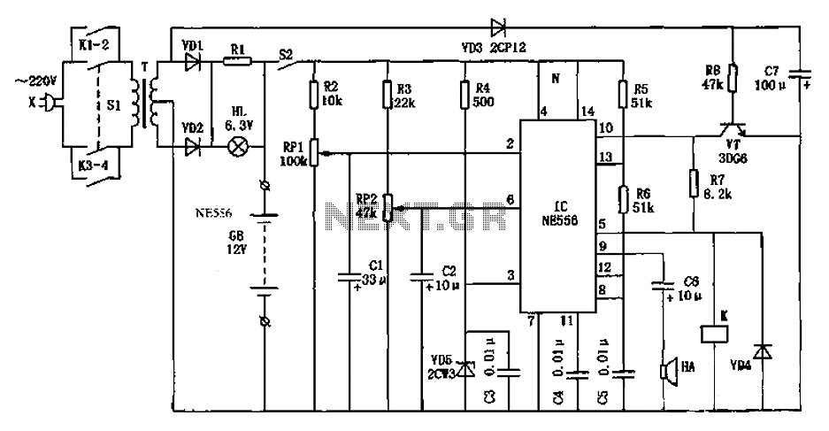
The circuit typically includes a battery voltage sensing mechanism, which continuously monitors the battery voltage levels. A microcontroller or comparator may be employed to assess whether the voltage is above or below a predefined threshold. If the voltage falls below this threshold, indicating a low battery condition, the circuit can trigger an alarm or an indicator light to alert the user.
Additionally, the circuit may incorporate a relay or a solid-state switch that can disconnect the battery from the load to prevent deep discharge, which can damage the battery. In some designs, a charging circuit can be integrated to automatically recharge the battery when it is detected to be below the optimal voltage level.
The schematic representation of this circuit would typically include components such as resistors, capacitors, diodes, and transistors, along with the microcontroller or comparator. Proper placement and connection of these components are crucial for the circuit's functionality, ensuring that signals are processed accurately and that the battery is effectively monitored and maintained.
Overall, the generator start battery automatic monitor circuit is an essential component for maintaining battery health and ensuring the reliable operation of generator systems. As shown in FIG generator start battery automatic monitor circuit diagram
Related Circuits
There are at least three different versions of this circuit. The first DM-2 version utilized the MN3005 BBD and the MN3101 Clock Driver IC (PCB marking: ET5214-510). Later, the clock driver was changed to the MN3102, and the BBD...
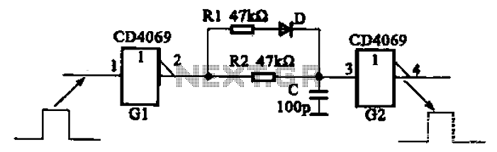
The inverter circuit using CD4069 is configured with a delay and width adjustment. When the output of the inverter (G1) is high, the capacitor (C) charges through resistor (R1) and diode (D). The voltage across capacitor C quickly reaches...
This page shows some methods of track routing control for Stall-Motor type switch machines. The principle method uses a 2 Pole - Multi Position rotary switch while an alternate uses optoisolators and transistors to select the routes. The last...
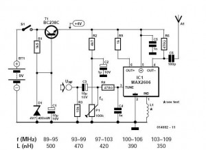
These do-it-yourself FM transmitters are relatively simple to construct and provide a satisfying experience when music is played through the radio receiver. Comments and links to additional designs that are not included in the best list are welcome. FM transmitters...
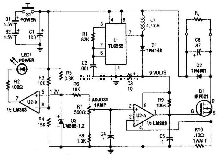
Useful for low-resistance measurements, this 1-A current source will produce 1 A in unknown resistance Rx. For best results, Rc should be less than 1 to 2, because only 3 V are available. Ul is a flyback converter to...
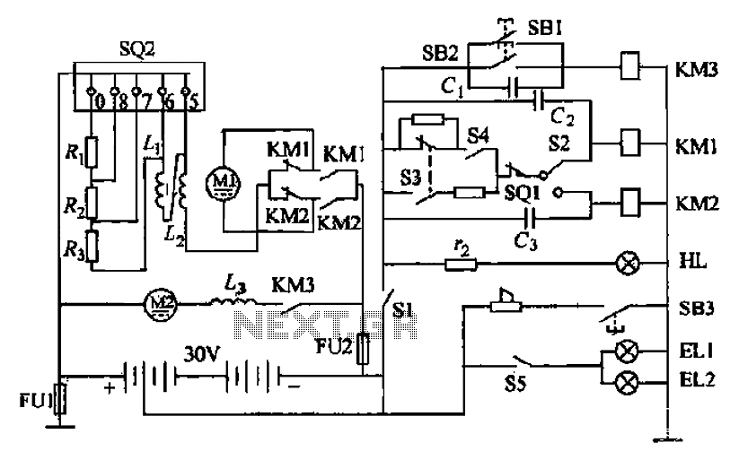
Battery forklifts are commonly used as stacking and handling tools in railway stations, docks, and warehouses. The battery shape and electrical control circuitry are depicted in the schematic. The system consists of batteries connected in series to form a...