
Automatic level control circuit diagram of six

The liquid level automatic controller circuit is designed to maintain desired liquid levels in reservoirs, ensuring efficient operation of pumping systems without manual intervention. The power circuit is crucial for converting high AC voltage to a manageable level for the control circuit. The use of a transformer allows for safe operation, while the rectifier diodes convert AC to DC, which is essential for powering the control execution components.
The level detection mechanism relies on the interaction of the electrodes submerged in the liquid. The electrodes serve as sensors that detect the liquid level changes. When the liquid touches the electrodes, it creates a conductive path that enables the control circuit to function. The integrated circuit (IC) plays a pivotal role in processing these signals and controlling the relay, which in turn manages the operation of the pump motor.
The selection of components is critical for the reliability and efficiency of the circuit. The resistors must handle the specified power ratings, and the capacitors should be chosen based on their voltage ratings to prevent failure under operational conditions. The use of silicon diodes ensures efficient rectification with minimal voltage drop, while the Zener diode provides voltage regulation to protect the circuit from voltage spikes.
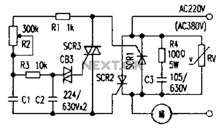
Overall, this circuit provides a robust solution for automatic liquid level control, suitable for various applications in industrial and agricultural settings where maintaining fluid levels is essential for operational efficiency. Circuit works The liquid level automatic controller circuit from the power circuit, a level detection circuit and control the implementation of circuit, as shown in FIG. Power circuit from the knife switch Q, fuse FU, power transformer T, rectifier diode VD1 ~ VD4, current-limiting resistors R1 and R5, filter capacitor C1 and Zener diode VS composition. Liquid level detection circuit by the high level electrode H, L low level electrode and the main electrode M components.
Control the implementation of circuit by the transistor V, relay K, when the base integrated circuit IC, diodes VD5 ~ VD8 RC components and peripherals. ON knife switch Q, AC 380V voltage by T Buck, when no liquid or liquid pool level is below the low level electrode L, no current rectifier circuit, the control circuit without the implementation of the operating voltage, the relay K is the release state, the normally closed contact connected to AC contactor KM power pull, plus pump motor M powered job and began dosing.
When the liquid level reaches the lower pool level electrode L, L low level electrode through the liquid in contact with the main electrode M, the rectifier circuit DC voltage output. The DC voltage by C1 filtering, R5 and VS limiting buck regulator to generate 12V DC voltage supply control execution circuit.
In this case, V in the off state, IC 2 feet and 6 feet are high, 3 feet output low, the relay K is not action, plus dosing pump motor M continues. FIG automatic level control circuit When the liquid level reaches the high level electrode tanks H, H high level electrode through the liquid and the main electrode traders turned on, so that V conduction, IC 2 feet and 6 feet into a low, 3 feet high output level, the relay K pull its normally closed contact K disconnect the AC contactor KM power release, plus pump motor M off the power supply, plus pump stops dosing.
When the reservoir pool level drops to a low level electrode L or less, input rectifier circuit and disconnect the control circuit to perform power lose their jobs, the relay K release, plus dosing pump again. Again and again, enabling unattended automatic liquid supply. Component selection R1 and R5 selects 27 wirewound resistors; R2 ~ M selected 1/4W metal film is electrically positive.
C1 selected voltage is 50V aluminum electrolytic capacitors; C2 use of electrolytic capacitors voltage is 25V for; C3 use monolithic capacitors or polyester capacitors. VD1 ~ VD8 selects 1N4001 or Model 1N4007 silicon diodes. VS selection of 1W, 12V zener diode, such as 1N4742 and other models. V selects C8050 or 58050,3DG8050 silicon NPN transistor. IC NE555 type used when the base integrated circuit. K selects JRX-13F type 12V DC relay. KM choose coil voltage is 220V AC contactor, the contact current capacity should be added according to pump motor power may be.
T use 5W, the second voltage of 18V (380V/18V) power transformer. You can use 1 level electrode inside the battery carbon rod (a metal cap on carbon rod with one end of the lead after a good weld, then epoxy sealing).
Related Circuits
This circuit diagram represents a radio-controlled system, commonly used in toy car applications for children. The circuit consists of two main parts: the transmitter and the receiver. The transmitter generates radio signals using an oscillator circuit formed by transistor...
The presentation of a general power thyristor trigger circuit is more complex, and some components are difficult to procure. A successful trigger circuit has been constructed for only a few dollars. This circuit is designed to trigger a thyristor...
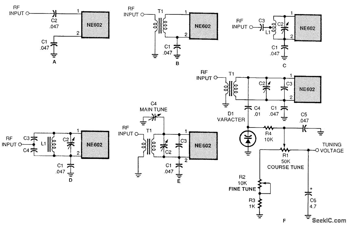
There are several methods to input a signal into the NE602. Simple untuned approaches (a and b) are viable. For tuning to a specific frequency, an LC resonant circuit with ungrounded trimmer capacitors (c and d) or grounded variable...
Circuit designed to alleviate concerns related to high frequency utilizes a ready-made module, specifically an Aurel audio FM transmitter. This compact circuit board, measuring 2 cm by 4 cm, supports a modulation frequency track and delivers an RF power...
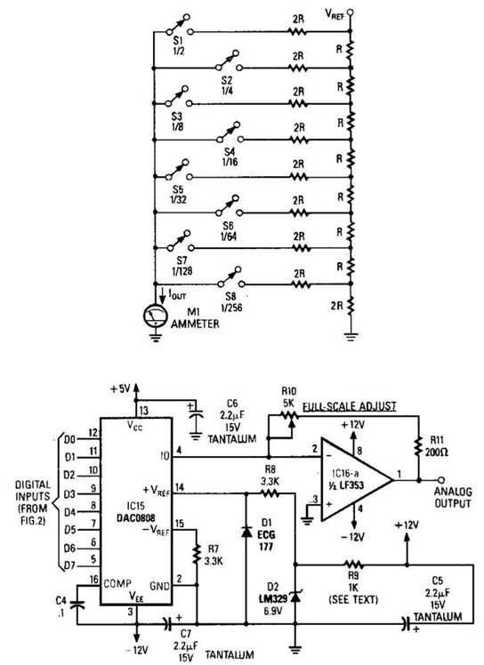
Figure A illustrates an R/2R resistor ladder. Each closed switch increases the current output. A basic channel A/D converter is depicted in Figure B. The voltage reference (D2) is shared among all channels, while the value of the dropping...
Circuit audio peak indicator circuit schematics. Circuit Electronics, schematics for audio peak indicator circuit. An audio peak indicator circuit is designed to visually represent the peak levels of an audio signal, providing critical information for audio engineers and musicians regarding...