
DC brush motor driver circuit diagram

The described DC brush motor driver circuit leverages the MC33035 integrated circuit, which is specifically designed for controlling DC motors in various applications. This chip provides the necessary drive signals to control the operation of the motor efficiently. The configuration includes a bridge driver circuit formed by field-effect transistors (FETs), which allows for bidirectional control of the motor.
In the forward rotation mode, the activation of transistor VT3 allows current to flow through the motor in one direction, resulting in forward movement. The reverse rotation is achieved by turning on transistors VT2 and VT4 simultaneously, which reverses the current flow through the motor, enabling it to rotate in the opposite direction.
This circuit design is particularly advantageous for applications requiring precise control over motor direction and speed. The MC33035 chip simplifies the control logic by integrating the necessary components into a single package, reducing the complexity of the circuit. Additionally, the use of FETs in the bridge configuration enhances the efficiency of the circuit by minimizing power losses and providing faster switching times, which is critical for applications demanding rapid changes in motor direction.
Overall, this DC brush motor driver circuit exhibits a robust design suitable for various automation and robotics applications, ensuring reliable performance and ease of integration into larger systems.DC brush motor driver circuit diagram MC33035 chip using a straight debate brush motor driving circuit ring shows a typical DC brush motor driver circuit diagram. 4 field effec t transistor bridge driver circuit, when the VTI, when the transistor VT3 conduction, the forward rotation of the drive motor; when VT2, VT4 when the transistor is turned on, the reverse rotation of the drive motor. Drive signal generated by the chip number MC33035.
Related Circuits
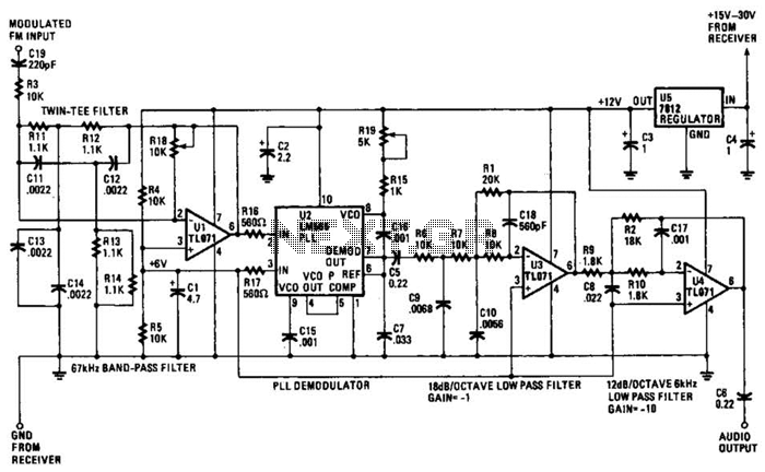
The operational amplifier (Op Amp) U1 and its associated components form a 67-kHz bandpass filter. A twin-T network, consisting of four 1100-ohm resistors and four 0.0022-microfarad capacitors, is integrated into the feedback loop of the op amp. This configuration...

The moderate power FM transmitter circuit employs two transistors. The voice signals picked up by the microphone will be amplified by the transistor. The described FM transmitter circuit utilizes two transistors to facilitate the modulation and amplification of audio signals....
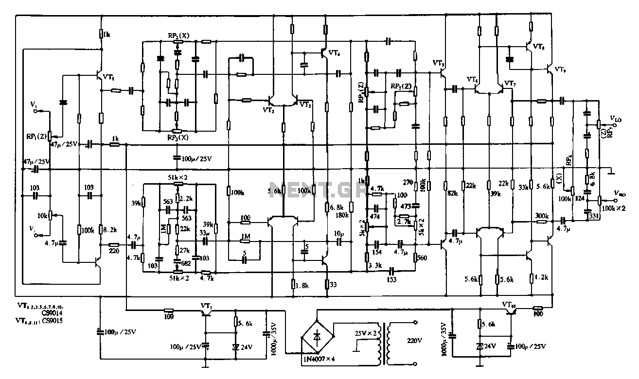
Figure 4-11 illustrates a feedback attenuator that comprises a transistor-based tone control circuit. This circuit features a conventional high and bass control system, along with balance control, volume control, loudness adjustment, and subwoofer control, as well as field sense...
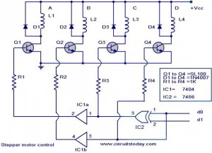
The following circuit illustrates a Stepper Motor Controller Circuit Diagram. This circuit is based on the 7404 IC. Features include a simple stepper motor. The stepper motor controller circuit utilizing the 7404 IC is designed to drive a stepper motor...
The circuit on this page is for a simple light detector circuit board that has 8 detectors that can be used with visible or infrared light systems. The detectors use LM339 voltage comparators as the active element. Phototransistors or...

This project involves using an EasyDriver stepper motor driver and a 1.8-degree per rotation stepper motor to achieve a motor speed of one revolution per minute. The EasyDriver simplifies the operation, requiring a DC voltage of 7-30V connected to...