
two-speed motor contactor control circuit two speeds in the same direction
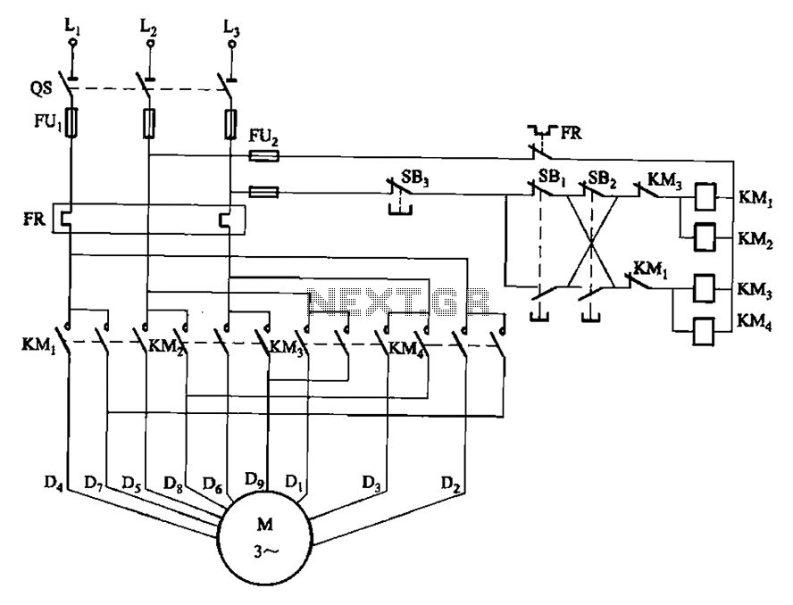
The circuit design incorporates two operational buttons, SBi and SBz, that control the speed of a motor or similar device. SBi is designated for the first speed setting, while SBz is utilized for the second speed setting. Both buttons are configured to allow the device to operate at two distinct speeds in the same directional flow, enhancing versatility in applications that require varying operational speeds.
In typical implementations, SBi and SBz may be connected to a motor driver circuit that interprets the button presses and adjusts the power supplied to the motor accordingly. The circuit could utilize a microcontroller or a dedicated speed controller IC to manage the input from the buttons and modulate the output to the motor.
The first speed setting, activated by SBi, may provide a lower voltage or PWM (Pulse Width Modulation) signal to the motor, resulting in a slower rotational speed. In contrast, the second speed setting, controlled by SBz, could increase the voltage or modify the PWM duty cycle, allowing for a higher speed operation.
Additionally, protective components such as diodes may be included to prevent back EMF generated by the motor from damaging the circuit. Capacitors may also be employed to filter noise and stabilize the voltage supply, ensuring smooth operation at both speed settings.
This circuit design is applicable in various scenarios, including robotics, conveyor systems, and other automated machinery where speed control is essential for performance optimization. Circuit shown in Figure 3-112. Figure, SBi as the first speed operation button, SBz is run by the second speed class. Two speeds in the same direction.
Related Circuits
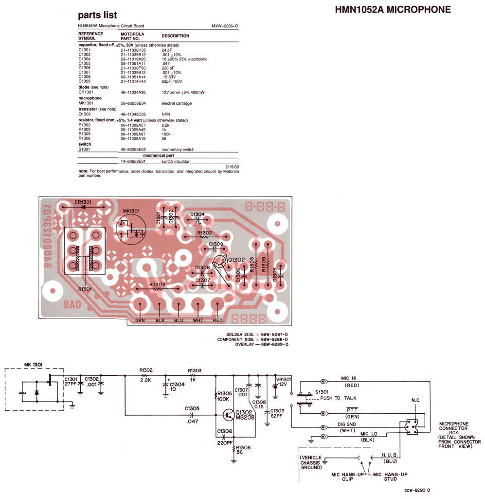
Regardless of the label on the radio or the claims made by the seller, no Spectra radio will function across the entire 136-174 MHz (high band) or 403-512 MHz (UHF) frequency range. Each unit operates within a specific portion...
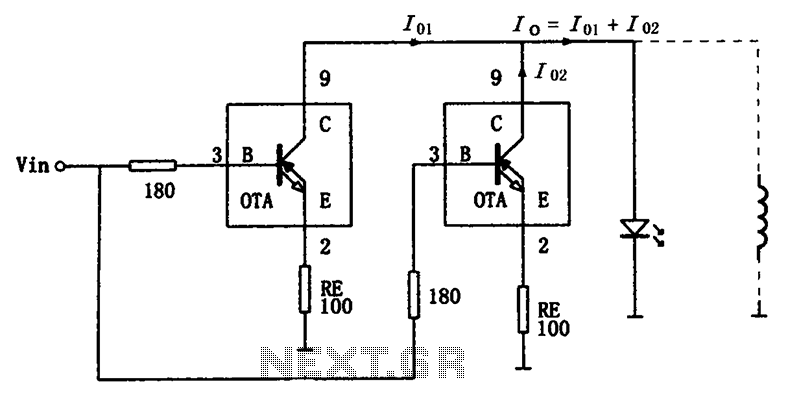
The high-speed parallel current drive circuit utilizes the OPA660 operational transconductance amplifier (OTA). An input signal, Vin, is connected to a 180-ohm resistor equivalent device at the base (pin 3) of the OPA660. The collector (pin 8) is directly...
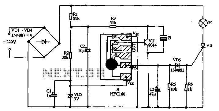
220V AC power is supplied through a VD1 to VD4 bridge rectifier and a voltage regulator circuit involving R1, R2, and VD5 components. The output provides a DC voltage of approximately 3V, which powers the manifold A. The manifold...
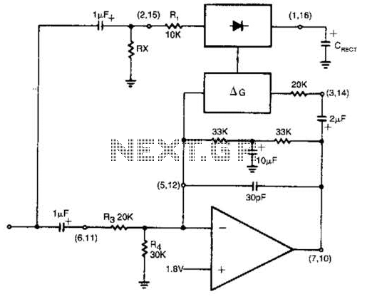
The rectifier input is connected to the input, establishing a relationship where gain is inversely proportional to the input level. Consequently, a 20-dB reduction in input level results in a 20-dB increase in gain. The output is designed to...
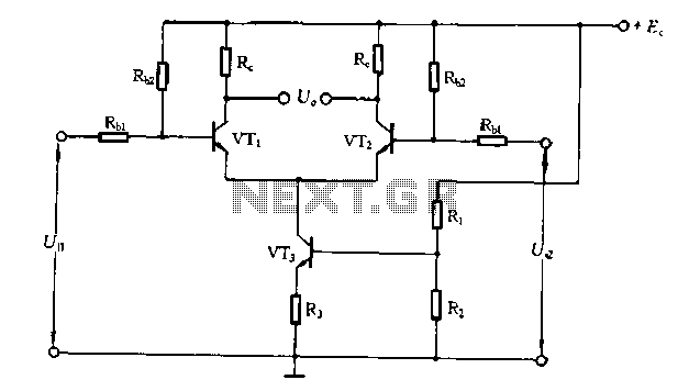
The differential amplifier circuit features a constant current source. The differential amplifier is a fundamental building block in analog electronics, utilized for amplifying the difference between two input voltages while rejecting any signals that are common to both inputs. Central...
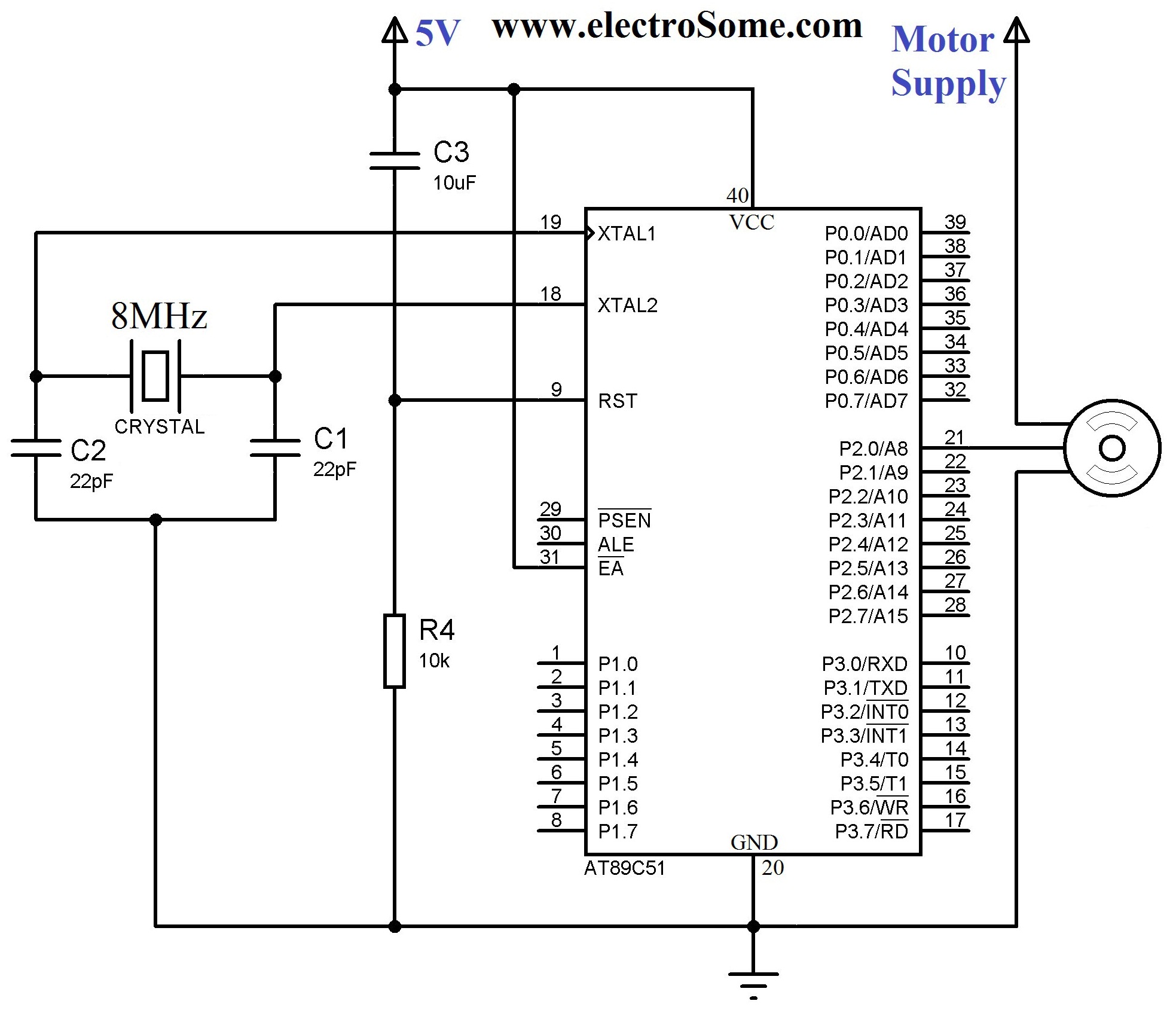
A servo motor employs a servo mechanism, which is a closed-loop system that utilizes position feedback to accurately control the angular position of its shaft. Stepper motors, which operate as an open-loop system, can also achieve precise angular control,...