
AVR/51 Development board

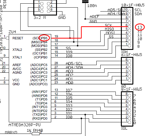
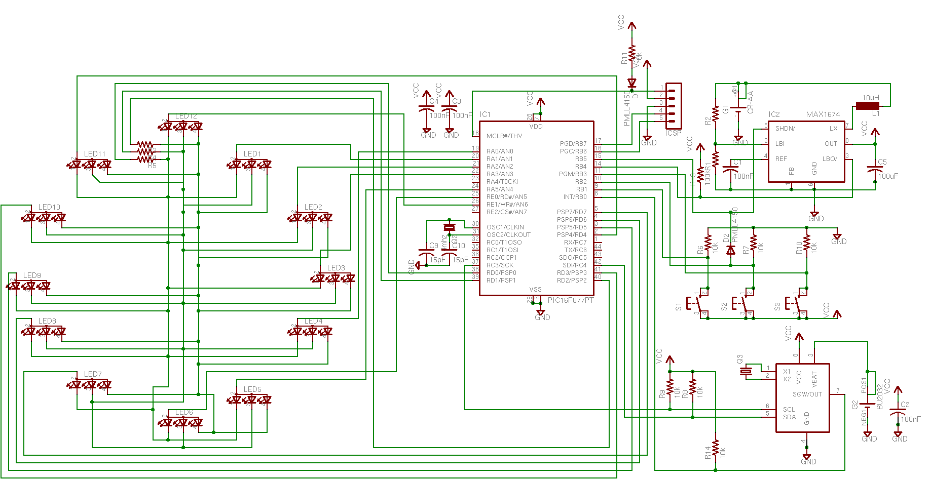
KiCad is a powerful open-source software suite that allows engineers and hobbyists to design electronic circuits and printed circuit boards (PCBs). It provides a user-friendly interface for creating schematic diagrams, where components such as resistors, capacitors, and integrated circuits can be placed and interconnected. The software supports various file formats for exporting designs and can generate Gerber files, which are essential for PCB manufacturing.
In the circuit diagram created in KiCad, each component is represented by standardized symbols, and the connections between them are depicted using lines. This visual representation aids in understanding the functionality of the circuit. The schematic can include annotations, such as component values and designators, which help in identifying and assembling the circuit accurately.
Furthermore, KiCad offers simulation capabilities, allowing users to test the circuit's behavior before fabrication. This feature is critical for verifying the design and ensuring that it meets the desired specifications. After finalizing the schematic, users can transition to the PCB layout stage, where they can arrange components on a virtual board and define the routing of electrical connections.
Overall, KiCad serves as an essential tool for anyone involved in electronics design, providing a comprehensive platform for creating, testing, and preparing circuits for production.I made circuit diagram in Kicad (In my opinion the best freeware software for drawing electronic diagrams and printed circuits boards). For printing.. 🔗 External reference
Related Circuits
The wire connected to the 5V pin is linked to the positive pins of the breadboard, which are not connected to any other components. There are no additional connections on the positive column. While this may seem like a...
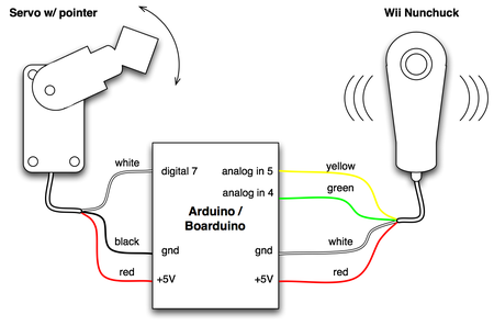
The small footprint of the Boarduino prompted an exploration into how compact a device could be created in one hour using various complex components. The combination of a Boarduino, a Wii Nunchuck, and a hobby servo motor was chosen...
Ensure to verify all connections utilizing the circuit diagram and breadboard schematic available for download from the provided links. This resource can assist during the assembly process. To create a reliable electronic circuit, it is essential to meticulously verify all...
The board has been initially developed to learn with CAN, so a CAN transceiver is available (IC4). The CAN transceiver comes from Maxim, but some other manufacturers provide some compatible CAN transceivers which can be used. An RS232 transceiver...
The doorbell button was replaced with a lighted version, but the chime continued to sound after the button was pressed. These lighted buttons incorporate an incandescent bulb in parallel with the button, a component that has been modified in...
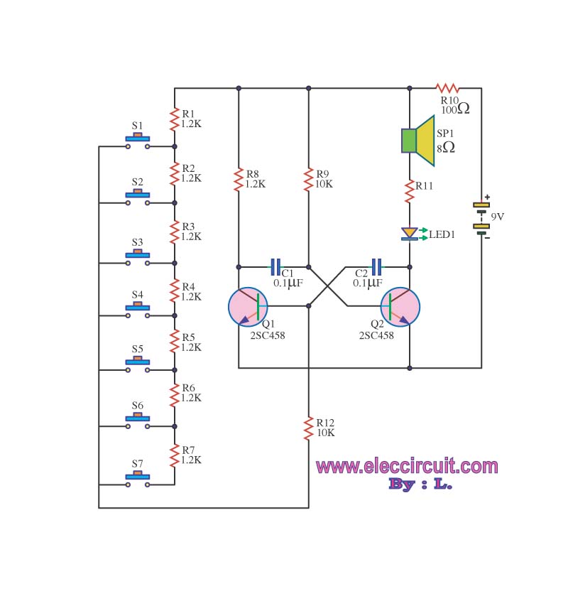
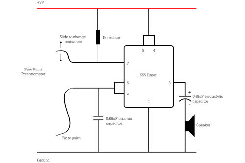
The circuit operates as an astable multivibrator, generating a square wave signal at a specific frequency. When powered, the circuit will function continuously. The astable multivibrator circuit is a type of oscillator that produces a continuous square wave output without...