
AVR-P40-USB-8535 BOARD FOR AT90S8535

RS232 interface: RS232 interface is designed around USB to RS232 converter IC FT232. More information about this IC can be found from the manufacturer's website http://www.ftdi.com. Proper drivers for your OS should also be downloaded from the same internet site. All RS232 modem signals are available around the FT232 IC for connection. RS232 Rx signal is connected directly to PD1 (AVR Tx) and RS232 Tx signal is connected directly to PD0 (AVR Rx).
Features:
- ICSP 5x2 pin connector for in-circuit programming with AVR-PG1B or AVR-PG2B
- JTAG port 5x2 for in-circuit debugging/programming with AVR-JTAG (ATJTAGICE)
- USB to RS232 FT232 converter
- I2C EEPROM socket
- Takes power from USB, no need for external adapter
- Power supply filtering capacitors
- Quartz crystal oscillator circuit 8 MHz
- Reset IC ZM33064
- Reset button
- General purpose push button
- Status LED connected to PB0 via removable jumper
- DIL40 microcontroller socket
- Extension pin headers for each uC pin
- Four mounting holes 3.3 mm (0.13")
- Grid 100 mils
- GND bus
- Vcc bus
- FR-4, 1.5 mm (0.062"), green solder mask, white silkscreen component print
- Dimensions 100x80 mm (3.9x3.15")
Supported devices: Supports all devices which are pin to pin compatible with AT90S8535 AVR microcontrollers. Power supply: Power supply is taken from USB port, so no need for external adapter.
The AVR-P40-USB programming and debugging tool integrates multiple functionalities for AVR microcontrollers, utilizing both ICSP and JTAG programming interfaces. The ICSP port allows for in-circuit programming through compatible dongles, with options for both serial and parallel connections, enhancing flexibility for various programming environments. The JTAG interface, featuring a 10-pin connector, provides comprehensive debugging capabilities, enabling real-time monitoring and control over the microcontroller’s resources, including memory and I/O modules.
The inclusion of the FT232 USB to RS232 converter facilitates seamless communication between the microcontroller and external devices, with direct signal connections ensuring minimal latency and reliable data transfer. The design incorporates essential components such as power supply filtering capacitors and a quartz crystal oscillator, which stabilize the microcontroller's operation.
Physical features of the AVR-P40-USB include a DIL40 microcontroller socket, extension pin headers, and a robust FR-4 PCB construction, ensuring durability and ease of integration into various projects. The device is powered via USB, eliminating the need for additional power adapters, thereby enhancing portability and convenience for developers. Overall, the AVR-P40-USB is a versatile tool that supports a wide range of AVR microcontrollers, making it suitable for both novice and advanced users in embedded system development.There are two ways to program AVR-P40-USB: with ICSP port and with JTAG port. To program via ICSP port you need serial port or parallel port AVR-ICSP programmer dongle (Olimex part # AVR-PG1B or AVR-PG2B). The serial port ICSP programmer (AVR-PG1B) works with PonyProg software by from Claudio Lanconelli and the latest release may be download for free from lancos.com The parallel port ICSP programmer (AVRPG2B) works with AVR ISP from Atmel and may be download for free from Atmels web site.
JTAG programming/debugging: AVR-JTAG (complete analog of ATMELs AVR JTAG ICE) is development tool for programming, real time emulation and debugging for AVR microcontrollers JTAG interface (ATmega16, ATmega32, ATMega323, ATmega162, ATmega169, ATmega128). AVRJTAG have: JTAG 10 pin connector (Atmel layout), status LED, RS232 connector. AVRJTAG allows access to all the powerful features of the AVR microcontroller. All AVR resources can be monitored: Flash memory, EEPROM memory, SRAM memory, Register File, Program Counter, Fuse and Lock Bits, and all I/O modules.
AVR-JTAG also offers extensive Onchip Debug support for break conditions, including break on change of Program memory flow, Program memory Break Points on single address or address range, and Data memory Break Points on single address or address range. JTAG interface: The JTAG connector is 2x5 pin with 0,1" step and Atmels compatible layout. The PIN.1 is marked with square pad on bottom and arrow on top. JTAG signals are: 1- TCK, 2- GND, 3- TDO, 4- VREF, 5- TMS, 6- NSRST, 7- VCC, 8- NTRST, 9- TDI, 10- GND.
RS232 interface: RS232 interface is designed around USB to RS232 convertor IC FT232. More information about this IC you can found from manufacturers web site http://www.ftdi.com. You should also download the proper drivers for your OS from the same internet site. All RS232 modem signals are available around FT232 IC for connection. RS232 Rx signal is connected directly to PD1 (AVR Tx) and RS232 Tx signal is connected directly to PD0 (AVR Rx) Features: · ICSP 5x2 pin connector for in-circuit programming with AVR-PG1B or AVRPG2B · JTAG port 5x2 for in-circuit debugging/programming with AVR-JTAG (ATJTAGICE) · USB to RS232 FT232 converter · I2C EEPROM socket · takes power from USB no need for external adapter · power supply filtering capacitors · Quartz crystall oscilator circuit 8Mhz · reset IC ZM33064 · reset button · general purpose push button · status LED connected to PB0 via removable jumper · DIL40 microcontroller socket · extension pin headers for each uC pin · four mounting holes 3.3 mm (0.13") · Grid 100 mils · GND bus · Vcc bus · FR-4, 1.5 mm (0,062"), green soldermask, white silkscreen component print · dimensions 100x80 mm (3.9x3.15") Supported devices: Supports all devices which are pin to pin compatible with AT90S8535 AVR microcontrollers. Power supply: Power supply is taken from USB port, so no need for external adapter 🔗 External reference
Related Circuits
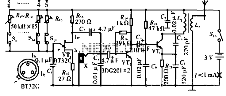
The circuit operates with VT3 and associated components arranged as a common-base capacitance feedback oscillation circuit. The oscillation frequency is set by capacitors C8, C9, and inductor L1. VT2 serves as a voltage amplification stage that reinjects the audio...
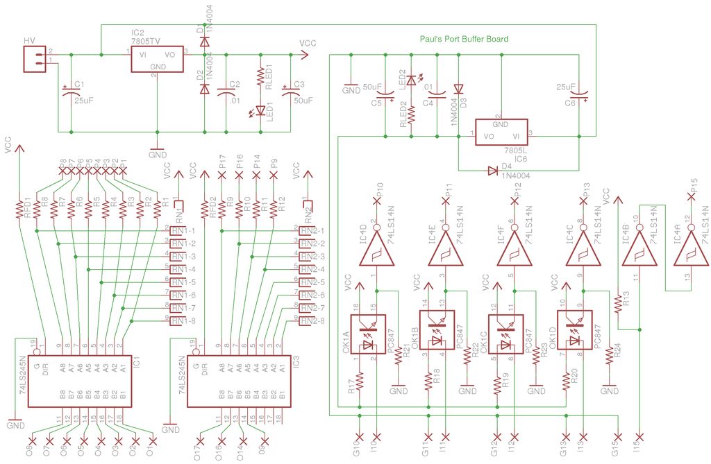
A buffer board was constructed with a specific project in mind, but it is being presented here as a general application device. The buffer board serves as an essential component in various electronic circuits, acting to isolate different sections of...
Here's PLL FM transmitter circuit from china. This circuit uses the familiar 2SC1971 for final power amplifier stage. The PLL controller of the FM transmitter use SAA1057 and PIC16F628 (download HEX file). More: If want to change the active...
Development board featuring high-power relays, opto-coupled inputs, a power supply circuit, a crystal oscillator circuit, and an RS232 port, along with ICSP and JTAG ports. The JTAG connector utilizes a 5x2 pin configuration for in-circuit programming. This development board is designed...
The controllable multivibrator, as illustrated in figure 14-40, consists of a 555 timer along with resistors RA, RP1, and capacitor C1. The oscillation frequency is influenced by the control voltage applied to pin 5. This control voltage is determined...
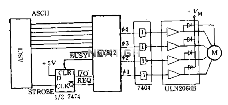
The CY512 is an easily developed system that operates using ASCII keyboard code. It features three operating modes: 1) Immediate command execution mode, where users can input ASCII commands to directly control the stepping motor movement in decimal stepping...