
balanced ground
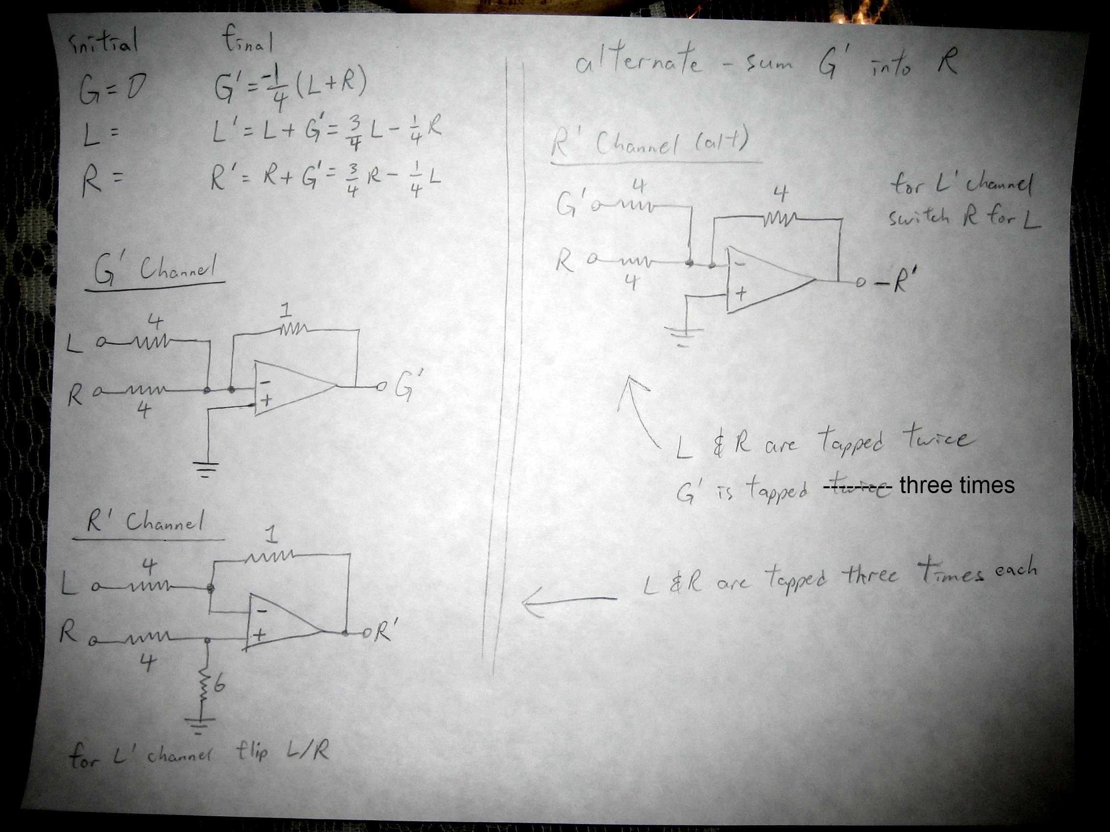
The proposed circuit design appears to be a complex approach to audio signal processing, employing operational amplifiers to manage the left (L) and right (R) audio channels effectively. The design philosophy suggests utilizing op-amps due to their inherent advantages in audio applications, such as low noise and high fidelity. The method of tapping the L and R signals multiple times introduces considerations regarding signal integrity and impedance matching, which are critical in maintaining audio quality.
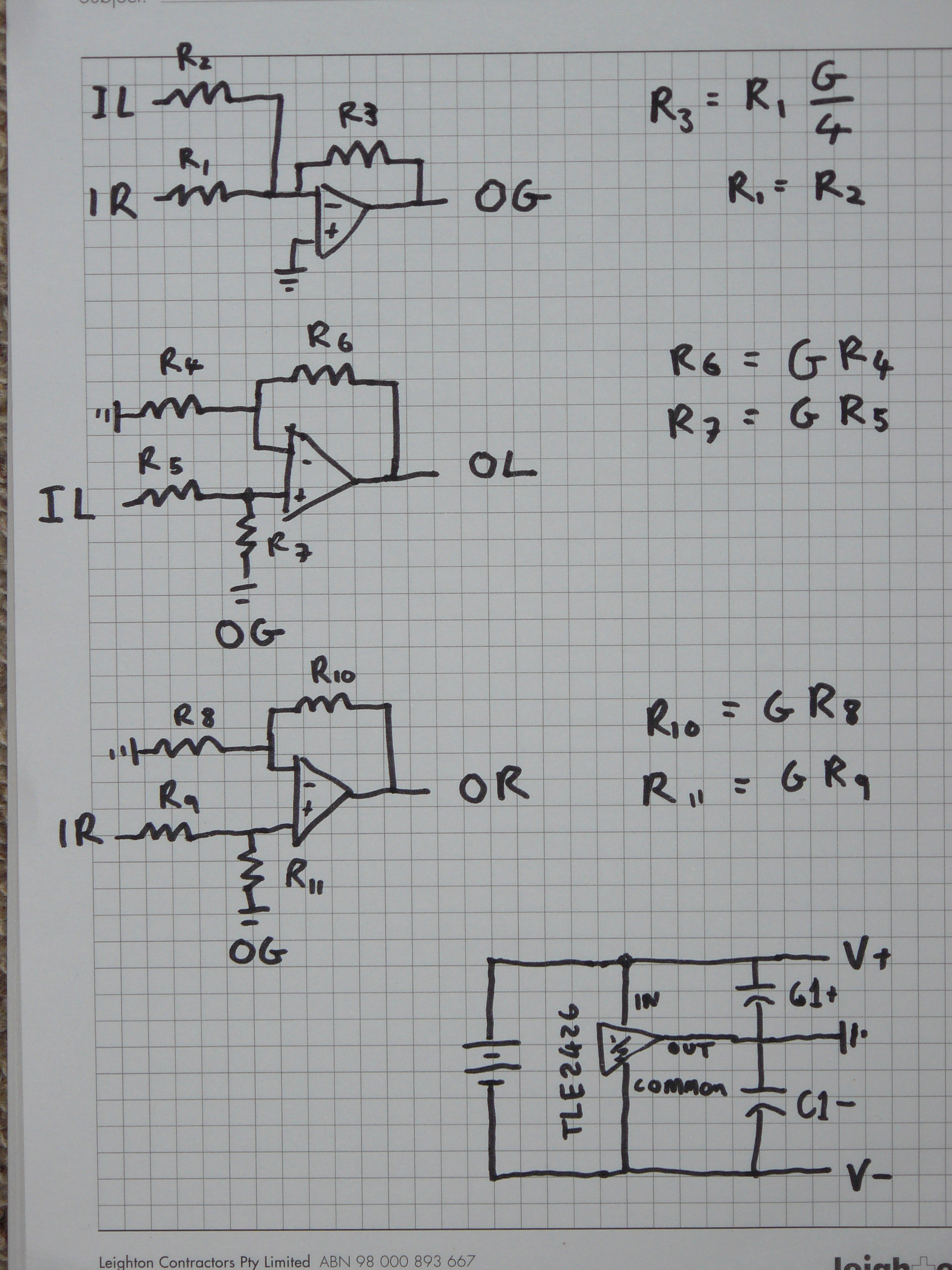
In this configuration, the original L and R signals are accessed at multiple points to create modified outputs (L' and R') while generating a ground reference signal (G'). The design also contemplates the use of feedback resistors, with specific values intended to maintain a balanced load across the system. The decision to use a three-wire approach instead of a four-wire configuration simplifies the design but necessitates careful calculation of resistor values to ensure proper function.
The circuit's performance is currently hindered by issues such as static noise and crosstalk, likely stemming from low-quality components and the breadboard's inherent limitations. The introduction of higher tolerance resistors and the use of capacitors for filtering may enhance stability and reduce noise. Furthermore, the potential for electromagnetic interference from external sources must be mitigated, possibly through shielding or improved layout techniques.
In conclusion, while the circuit demonstrates innovative ideas in audio signal processing, practical implementation challenges must be addressed to achieve the desired performance. Ongoing adjustments and refinement of component selection and circuit layout will be essential in advancing this project toward a successful outcome.Seems to me it uses at least as much power and at least as many components as a 4 channel balanced amp. it may well sound realy good and its quite clever, but does seem like a lot of trouble to go to `to travel the path less travelled` all the sameit really is quite interesting, so i`ll be watching on to see how it goes, you may think its easier to do with discrete SS devices like jfets, but opamps are
basically made for this kind of job, so use them to the fullest IMO and there are some really nice sounding ones these days too, if well implemented Why would you need to double the ground channel You`re tapping two sets of wires off it, so your voltage is the same in each except now you have two of them, so it all balances out. just because there is 2 wires does not mean there is double the signal strength, the way I see it you would indeed need to either double the channel, or double the signal strength and tap twice; tapping a single channel twice will simply give you half the signal strength on each wire Er.
we`re tapping a voltage signal correct Tapping it twice does not diminish that signal. The channel will need to pump out more power since it`s feeding both sides, but the signal remains the same. An issue I see though is that since loading is complex and impedance changes with signal, things might imbalance.
but I guess this is a problem inherent in a normal setup anyways and isn`t something that can be accounted for (at least not with my limited knowledge of amp and headphone design). Doing it this way means we tap the original L and R three times each. Resistor values (all relative) chosen for simplicity and so that all three present the same load (I think), though I have no idea if that makes a difference going into an opamp.
Alternatively (and I don`t know if this is better or not), create the G` signal then add that into the original L and R to get -L` and -R` respectively. Invert while amping later as appropriate. The L and R signals only get tapped twice this way, but the G` gets tapped three times (once each to create L` and R`, and again for the final amping).
edit: and if going by that "3 wire" thing that I was yammering about instead of the assumed 4 wires, then change the feedback resistor to 1. 333 and the ground resistor to 4. Results: well. it works, but it`s not pretty right now. It works mechanically (uh, electrically ) but I`ve got static/buzzing and crosstalk pushing through which is disrupting things.
I`ve also got the physical limitation of cheap parts. The breadboard is kinda spotty at times (especially the power rails) and I got a big box of cheap resistors that are 5% tolerance, so the matching is rather poor. Plus outside EM interference (heck, I can pick up radio signals if I listen closely). I`m guessing there`s a bit of time delay/phase shift too, which means some of the signals don`t quite perfectly cancel when they`re supposed to.
I also compared connecting the headphones to G* vs original G. Connected to G, my channels were mixed (as expected). Connecting to G*, they were "normal" except for the static. But what do you guys think Is this worth pursuing I`m really at the limits of my knowhow right now. I`m sure capacitors somewhere would help, or fitting it all onto a protoboard and reduce the clutter, or increase the resistors What happens when I tap an output multiple times Does the signal decrease or does it stay the same (I assumed that tapping voltage signals doesn`t affect the signal strength, only current, which I *think* isn`t a concern if we keep everything small enough) I`ve been fidgeting around with the circuit and got rid of a lot of the static with 50k ground resistors at the three outputs (still picking up radio though). I think now it`s mainly trying to get the right balance so the G* properly cancels out. edit: a 🔗 External reference
Related Circuits
The design aims for a higher output voltage swing for the mono part of the signal. There is skepticism regarding the proposed method due to potential crosstalk issues unless resistors are precisely matched. A schematic was planned where G...
Well, it's pretty much a PAiA preamp - usual input circuitry followed by one half of dual op-amp rigged in fixed 20dB amplification circuitry, followed by second stage which is adjustable for up to 40dB amplification, for up to...
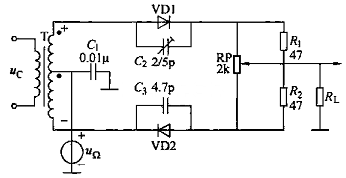
A common diode balanced modulator circuit is illustrated. It comprises two identical performance diodes and a center-tapped transformer configuration. The diodes used are VD1 and VD2, specifically 2AP9 models. The parameters for the circuit elements are detailed in FIG....
Combines signals from loop and sense antennas of an automatic direction finder to produce a 130-cps output with the correct phase for driving the rotor of a resolver to achieve a null position. The circuit described is integral to the...
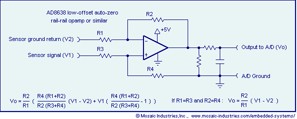
Ground loop offset errors and ground noise are eliminated by a differential amplifier or instrumentation amplifier before the analog-to-digital (A/D) conversion. The differential input amplifier addresses ground loop errors, allowing for precise measurement of non-isolated sensors. A simple operational...
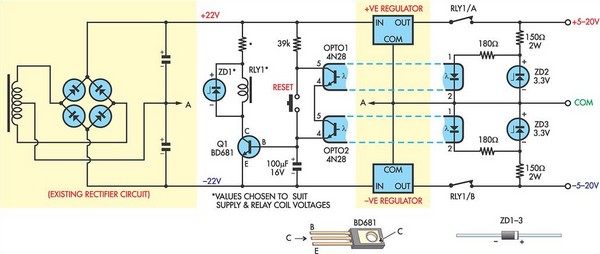
This circuit was designed to protect a dual rail power supply from shorts across the two rails. It uses an optocoupler to monitor each supply rail, with the internal LEDs powered from ZD2 and ZD3 and the associated resistors....
Warning: include(partials/cookie-banner.php): Failed to open stream: Permission denied in /var/www/html/nextgr/view-circuit.php on line 713
Warning: include(): Failed opening 'partials/cookie-banner.php' for inclusion (include_path='.:/usr/share/php') in /var/www/html/nextgr/view-circuit.php on line 713