
Band Pass Filters

A band-pass filter serves as an essential component in various electronic applications, particularly in communication systems, audio processing, and signal analysis. The design of these filters can vary significantly based on their intended use. For wide band-pass filters, the design typically focuses on achieving a broad frequency response while maintaining acceptable levels of attenuation outside the passband. Cascading first-order high-pass and low-pass filters results in a filter that is easy to implement and offers satisfactory performance for many applications.
In contrast, narrow band-pass filters are often employed in scenarios where precise frequency selection is critical, such as in radio frequency (RF) applications or in narrowband communication channels. The use of operational amplifiers in narrow band-pass filter designs allows for enhanced performance characteristics, including improved gain stability and reduced distortion. The multiple feedback configuration is particularly advantageous as it allows for fine-tuning of the center frequency and quality factor without necessitating extensive redesign of the circuit.
The calculation of the components in a narrow band-pass filter involves determining the values of resistors and capacitors based on the desired center frequency and bandwidth. The relationships governing these parameters ensure that the filter can be tailored to meet specific performance criteria. The ability to change the center frequency by adjusting resistor values provides flexibility in design, making it easier to adapt the filter to different operational requirements.
Overall, band-pass filters play a crucial role in signal processing by allowing only desired frequency components to pass through while effectively rejecting unwanted signals. Their versatility and adaptability make them indispensable in modern electronic systems.A band-pass filter is a circuit which is designed to pass signals only in a certain band of frequencies while attenuating all signals outside this band. The parameters of importance in a bandpass filter are the high and low cut-off frequencies (fH and fl), the bandwidth (BW), the centre frequency fc, centre-frequency gain, and the selectivity or Q
. There are basically two types of bandpass filters viz wide bandpass and narrow bandpass filters. Unfortunately, there is no set dividing line between the two. However, a bandpass filter is defined as a wide bandpass if its figure of merit or quality factor Q is less than 10 while the bandpass filters with Q > 10 are called the narrow bandpass filters. Thus Q is a measure of selectivity, meaning the higher the value of Q the more selective is the filter, or the narrower is the bandwidth (BW).
The relationship between Q, 3-db bandwidth, and the centre frequency fc is given by an equation For a wide bandpass filter the centre frequency can be defined aswhere fH and fL are respectively the high and low cut-off frequencies in Hz. In a narrow bandpass filter, the output voltage peaks at the centre frequency fc. A wide bandpass filter can be formed by simply cascading high-pass and low-pass sections and is generally the choice for simplicity of design and performance though such a circuit can be realized by a number of possible circuits.
To form a ± 20 db/ decade bandpass filter, a first-order high-pass and a first-order low-pass sections are cascaded; for a ± 40 db/decade bandpass filter, second-order high- pass filter and a second-order low-pass filter are connected in series, and so on. It means that, the order of the bandpass filter is governed by the order of the high-pass and low-pass filters it consists of.
A ± 20 db/decade wide bandpass filter composed of a first-order high-pass filter and a first-order low-pass filter, is illustrated in fig. (a). Its frequency response is illustrated in fig. (b). A narrow bandpass filter employing multiple feedback is depicted in figure. This filter employs only one op-amp, as shown in the figure. In comparison to all the filters discussed so far, this filter has some unique features that are given below.
Generally, the narrow bandpass filter is designed for specific values of centre frequency fc and Q or fc and BW. The circuit components are determined from the following relation ships. For simplification of design calculations each of C1 and C2 may be taken equal to C. The centre frequency fc of the multiple feedback filter can be changed to a new frequency fc without changing, the gain or bandwidth.
This is achieved simply by changing R2 to R`2 so that 🔗 External reference
Related Circuits
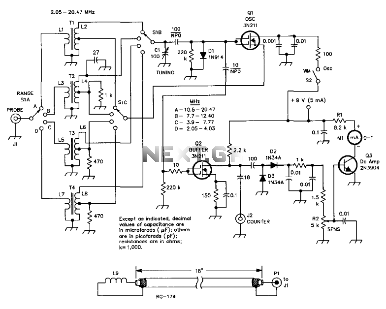
This circuit is designed for checking resonances in tuned circuits, antennas, and similar applications, covering a frequency range of 2 to 20 MHz. Q1 acts as an oscillator that can be tuned across this range using capacitor C1 and...

This circuit is a graphic equalizer that can be built with a low component count and is controlled using the LA3600 single IC chip. The internal design of the chip utilizes a transistor gyrator circuit, with connections to external...
Electronics tutorial about passive high pass filter circuit, including passive RC high pass filter first order frequency response, Bode plot, and construction. The passive high pass filter circuit is an essential component in electronics, designed to allow signals with a...
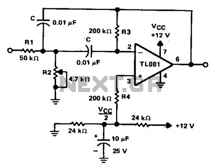
The circuit is a two-pole active filter utilizing a TL081 operational amplifier. This type of circuit is applicable only for quality factors (Qs) less than 10. The component values for this filter are determined using specific equations. The two-pole active...
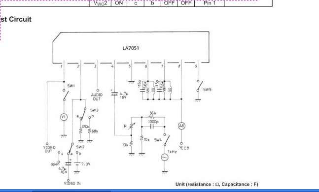
The LA7051 is a video and audio signal processor integrated circuit (IC) designed for UHF band RF modulation. It performs functions such as audio frequency modulation, video clamping, and white clipping. The LA7051 IC is engineered to facilitate the modulation...
Seeking the appropriate resistor and capacitor values for a low-pass filter designed to eliminate radio frequency (RF) interference. The application focuses on filtering out unwanted untuned RF signals from a crystal radio set. A low-pass filter is an essential component...