
LA7051 Audio Signal Processor For Uhf Band Rf Modulator

The LA7051 IC is engineered to facilitate the modulation of audio and video signals for transmission over UHF frequencies. It integrates multiple functionalities into a single package, making it a versatile choice for RF modulation applications.
The audio FM modulator within the LA7051 allows for the efficient encoding of audio signals onto a carrier frequency, enabling clear transmission of sound alongside video content. The video clamp circuit is responsible for stabilizing the video signal levels, ensuring that the output remains within the desired amplitude range. This is crucial for maintaining video quality and preventing distortion during transmission.
Additionally, the white clip circuit serves to limit the peak levels of the video signal, effectively preventing saturation and ensuring that the transmitted image retains its integrity. This clipping action is particularly important in scenarios where bright highlights could otherwise lead to signal distortion.
Overall, the LA7051 is a compact and efficient solution for integrating audio and video processing in RF modulation systems, contributing to improved performance in broadcasting and communication applications. Its design supports seamless integration into various electronic systems, providing reliable and high-quality signal processing capabilities.The LA7051 is a video, Audio signal processor IC for UHF band RF Modulator It performs the functions of Audio FM Modulator video clamp circuit, white clip circuit.. 🔗 External reference
Related Circuits

When switches SW1, SW2, or SW3 are open, the input sensitivity is optimized for high-output devices such as CD players, tuners, tape recorders, iPods, miniDisc players, and computer audio outputs. The 750 Ohm value for resistors R3, R13, and...

This is a low watt audio amplifier with a different technique in design. The 1.8K resistor has been connected to output of the circuit instead of VCC line. The output power of the circuit is about 250mW on an...
If one has considered experimenting with pulse-width modulation, this circuit serves as an excellent starting point. The design prioritizes simplicity by utilizing a dual 555 timer, making the assembly straightforward. A small PCB has been created for this purpose,...
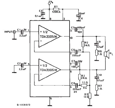
TDA2005 car audio amplifier circuit diagram electronic project using few external electronic parts The TDA2005 is a robust integrated circuit designed for audio amplification in automotive applications. This circuit diagram outlines a project for a car audio amplifier that utilizes...
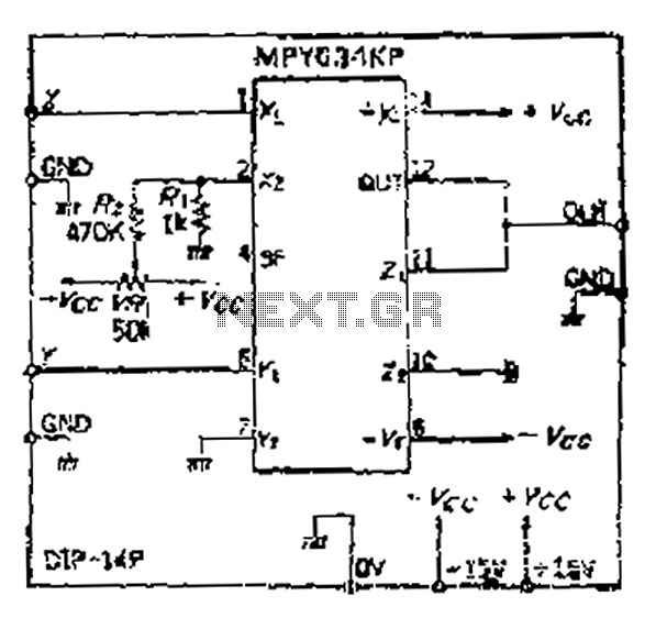
Although the inputs are differential, the right amplifier has a bias current greater than 800 nA. Therefore, the input coupling capacitor should be considered. It is important to note that the resistance value on the input side should also...
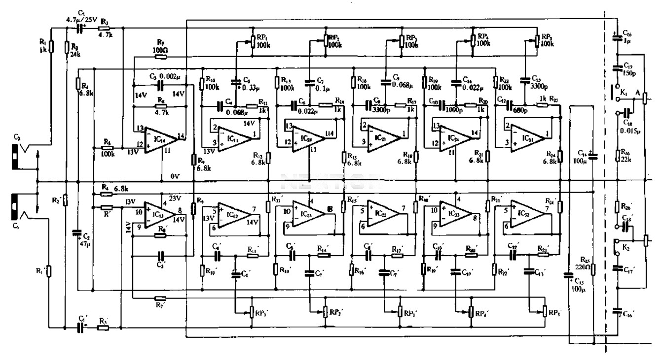
Figure 1-98 illustrates a double five-band equalizer circuit featuring a secondary connection. In this configuration, IC1 and IC14 serve as voltage amplifiers for each channel of the equalizer. The circuit also includes IC11, IC24, IC2, IC34, IC31, IC12, IC23,...