
IC 723 Voltage Regulators-WorkingCircuit Applications

The IC 723 is a voltage regulator integrated circuit that is widely used for providing a stable output voltage. It is capable of delivering output currents up to 1.5 A and can operate over a wide input voltage range, typically from 3 V to 40 V. The device features adjustable output voltage capabilities, allowing for a range of output voltages from 1.25 V to 37 V through the use of external resistors.
The block diagram of the IC 723 outlines its primary functional components, which include a voltage reference, error amplifier, output driver, and current limiting circuitry. The voltage reference provides a stable reference voltage, which is crucial for maintaining output accuracy. The error amplifier compares the output voltage to the reference voltage and adjusts the output driver accordingly to ensure that the output voltage remains constant under varying load conditions.
The output driver is responsible for supplying the necessary current to the load, while the current limiting circuitry protects the regulator from excessive current draw, thereby preventing damage to the IC. Additionally, the IC 723 includes thermal shutdown features to safeguard against overheating.
Applications of the IC 723 span various fields, including power supplies for electronic devices, battery chargers, and voltage regulation in industrial equipment. Its versatility and reliability make it a popular choice among engineers for designing stable power supply circuits.
In circuit design, the IC 723 can be configured in both linear and switching applications, depending on the requirements of the specific application. Proper selection of external components, such as capacitors and resistors, is essential for optimizing performance and achieving the desired output characteristics.The working and block diagram of IC 723 Voltage Regulators is given with Circuit Diagram, and Applications,.. 🔗 External reference
Related Circuits
The AD537 is a monolithic voltage-to-frequency (V-F) converter that includes an input amplifier, a precision oscillator system, an accurate internal reference generator, and a high-current output stage. A single external resistor-capacitor (RC) network is sufficient to configure any full-scale...
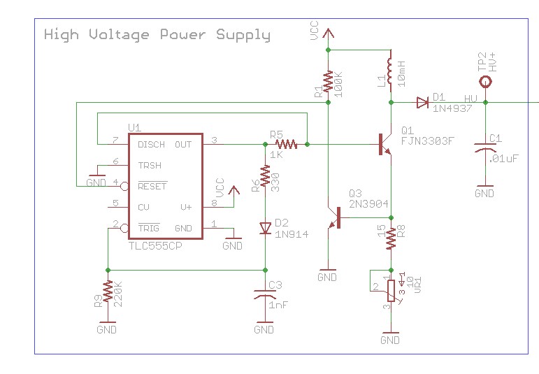
The design involves using a 555 timer as an oscillator in the high voltage power supply section. There is a query regarding the possibility of altering the design to utilize an output from a microcontroller to generate an oscillating...
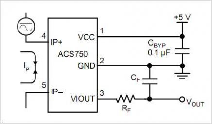
This is a CMOS IC (CD4033) based circuit which can be used to detect presence of mains AC voltage without any electrical contact with the conductor carrying AC current/voltage. Thus it can be used to detect mains AC voltage...
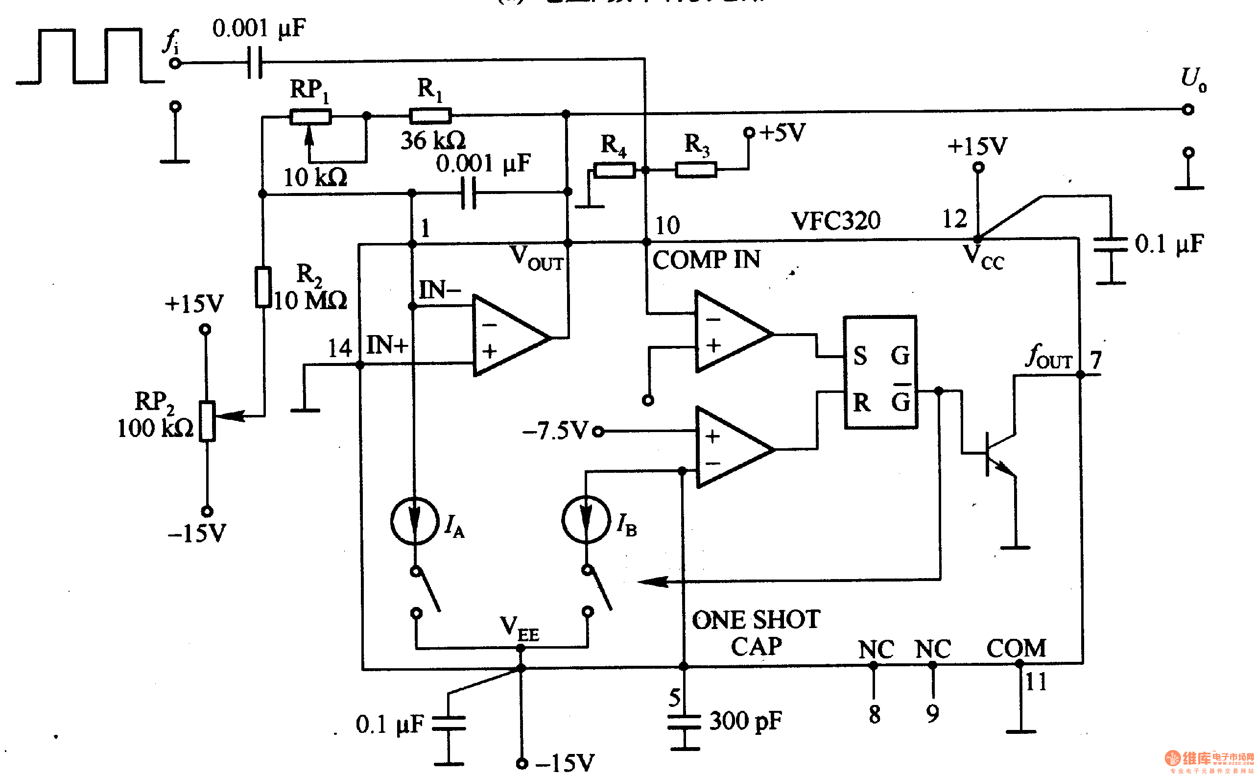
Figure 1-22 (a) illustrates a circuit that converts an input voltage of 0 to +10V (Ui) into a pulse with an output frequency ranging from 0 to 100kHz. In this configuration, pin 7 of the VFC320 is connected to...
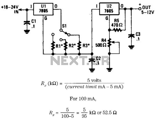
This voltage regulator and current limiter combination can be constructed using two 7805 regulators as illustrated. Resistors R1, R2, and R3 should be chosen to achieve a 5-V drop at the maximum allowable current limit. Switch S1 selects one...
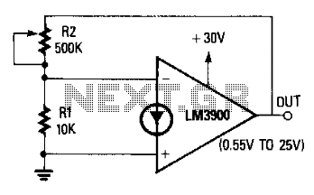
The non-inverting terminal of the operational amplifier (op-amp) is grounded, and the circuit utilizes the voltage at the inverting terminal as a reference. The voltage gain of the circuit is determined by the ratio of resistors R2 to R....