
Switching (transformerless) DC/AC 12V/230V 150W modified sine wave inverter
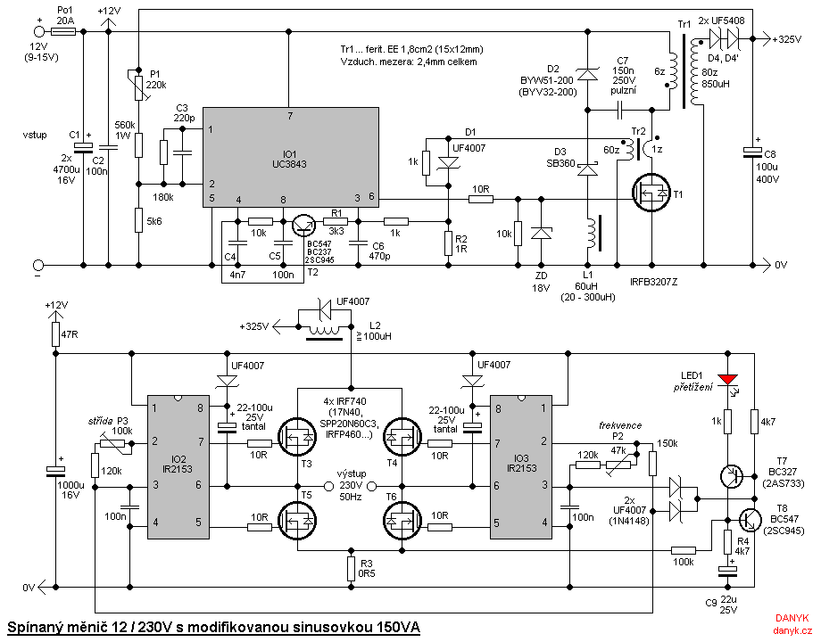
The circuit of a switching inverter with a modified sine wave typically consists of two main components: 1) a DC/DC converter that boosts the DC input voltage (12V, 24V, or 48V) to a high DC voltage corresponding to the mains voltage amplitude (approximately 325V for 230V AC) and 2) a polarity switching bridge that converts this elevated voltage into a modified sine wave. For lower output power switching converters (up to around 150W), the DC/DC converter can be implemented as a flyback supply. For higher power applications, a push-pull supply configuration is necessary, although this introduces significant complexity due to the high secondary voltage. A single-coil step-up inverter is not suitable due to the excessively high step-up ratio. Consequently, the DC/DC converter is designed as a flyback supply. The detailed description of the DC/DC section is omitted as it has been previously documented.
The inverter bridge comprises N-channel MOSFET transistors: T3, T4, T5, and T6. Their operation is controlled by integrated circuits IO2 and IO3, specifically the IR2153 type. The IR2153 serves as an integrated half-bridge driver with an internal oscillator. Here, the oscillator in IO3 operates as the master oscillator at a frequency of 50 Hz, while IO2 functions as a slave, with its oscillator section utilized as a phase shifter relative to IO3. To create a modified sine wave capable of managing inductive loads, it is essential to block (short circuit) the output during periods of zero output voltage. This is accomplished by switching two transistors in the bridge—either both lower or both upper transistors. For optimal loss distribution, it is preferable to alternate between the top and bottom pairs. The most effective method is to use two rectangular signals with a phase shift; at an input voltage of 325V, a 230V RMS output voltage is achieved with a 90° phase shift, resulting in a 25% duty cycle. Alternative duty cycles may be selected, such as 30% at 297V input or 33.3% at 282V input.
The DC/DC converter is adjustable via trimmer P1. It is advisable to test and calibrate the DC/DC converter independently. For a 25% duty cycle, P1 should be adjusted to achieve a 325V output from the DC/DC converter. Trimmer P2 sets the output frequency, which can be measured at pin 2 of IO3, targeting 50Hz (or 60Hz for some regions, in which case a 120k resistor should be replaced with a 100k resistor). P3 is used to set the correct duty cycle. Caution is advised when using voltmeters (multimeters) that cannot measure the effective (RMS) voltage at the inverter output, as they may inaccurately display a lower voltage than the actual 230V output.
The inverter includes overload and short circuit protection. The current through the bridge is monitored by shunt resistor R3 and transistor T7. In the event of an overload or short circuit, T7 and T8 will activate, maintaining each other in an 'on' state. They apply a negative voltage to pins 3 of IO2 and IO3, triggering the shutdown (SD) feature, which keeps the bridge off until the input power is disconnected and reconnected. Given that many appliances draw a surge of power when turned on, a delay mechanism is implemented to prevent unnecessary shutdowns, managed by capacitor C9. This allows the inverter to tolerate short-term overloads without activating protection. However, in the event of a genuine short circuit, the inverter must deactivate swiftly. The current threshold for fast shutdown is set higher than that for delayed shutdown, which is determined by resistor R4, while R3 sets the threshold for delayed shutdown. Inductor L2 is employed to limit the dv/dt during short circuits; without it, protection would only guard against overloads, not short circuits. Under normal operating conditions, the voltage across L2 remains minimal. The activation of protection is indicated by LED1. The inverter operates with an efficiency exceeding 90%.
It is important to note that for 220V AC mains, the amplitude is 310V, while for 240V AC mains, the amplitude is 340V. Caution is necessary, as the inverter should be protected by an appropriate fuse. Although the inverter's input voltage is safe, its output voltage is dangerously high. Additionally, capacitors in the switching inverter can retain hazardous voltages even after the unit has been powered down. The inverter may not be suitable for certain appliances, and all actions taken with this device are at the user's own risk. No liability is accepted for any harm caused.The inverter is suitable for battery powering of mains appliances. It is a switching converter, which contains no bulky, heavy and expensive iron transformer. The advantage of small size and weight, precise output voltage stabilization and among other things, very little quiescent power consumption, which can not be achieved using th e classical transformer. The disadvantage is perhaps it is a little more complicated :). Use: Can be used for most appliances except those capacitive (eg. with high parallel capacitor) and those that require pure sine for another reason. Not suitable for capacitive limited mini fluorescent nigth lights and LED light bulbs. For the conventional fluorescent (or discharge) lights is necessary to disconnect the capacitor. Circuit Switching Inverter with modified sine wave typically consists of two parts: 1) DC/DC converter that increases the DC input voltage of 12V (24V, 48V) to the high DC voltage corresponding to about the mains voltage amplitude (for mains 230V~ it is 325V=) and 2) polarity switching bridge that turns this increased voltage into a modified sine wave. For lower output power switching converters (up to about 150W) the DC/DC converter can be built as flyback supply.
For more power would be necessary to use a push-pull supply (or forward, but the complication is very high secondary voltage). Single coil step-up inverter is not suitable, because the step-up ratio is too large. Due to the low power I have my DC/DC converter finally built as flyback supply. I will omit the detailed description of the DC/DC section, because this schematic has already been described in detail here: DC/DC converter 12V / 325V 150W.
The inverter bridge is composed of the transistors of MOSFET N type: T3, T4, T5 and T6. They are controlled by integrated circuits IO2 and IO3 of type IR2153. The circuit IR2153 is an integrated halfbridge driver with internal oscillator. IO3 oscillator works here as a master oscillator frequency 50 Hz. IO2 is a slave, its oscillator section is used as a phase shifter, depending on IO3. To make a modified sine wave bridge that could manage inductive loads, it is necessary to block (short circuit) the output while the zero output voltage. It is done by switching two transistors in the bridge - either both lower or both upper. For even distribution of losses it is obviously once the top and once the bottom pair. The best way to do this is using two rectangular singals with a phase shift. When the input voltage is 325V, the 230V rms output voltage is achieved with 90 ° shift, which is 25% duty cycle.
Sometimes in the converters, another compromise is selected, eg 30% duty cycle with the input voltage 297V, or 33. 3% with the input voltage 282V. DC/DC converter is set by the trimmer P1. DC/DC converter is recommended to be tested and adjusted independently. If we chose a 25% duty cycle, set P1 so that the output of DC/DC converter was 325V. P2 sets the output frequency. We measure the frequency of the IO3 pin 2 and set to 50Hz (for some countries it is 60Hz - I recommend to replace the 120k resistor by 100k it case of 60Hz).
Finally, use P3 to set the correct duty cycle. Warning - voltmeters (multimeters), which can not measure the effective (RMS) value of the voltage at the inverter output will not show correctly 230V, but a little less! Therefore, they are not suitable to set the duty cycle! Actual voltage would be higher than the measured! The inverter is protected against overload and short circuit. The current through the bridge is sensed by R3 shunt and T7 transistor. If an overload or short circuit, the T7 and T8 subsequently turns on. T7 to T8 keep each other open. They bring negative voltage on pins 3 of IO2 and IO3, which activates the shutdown (SD) and the bridge will remain off until disconnecting and reconnecting input power of the inverter.
Given that most appliances creates a power surge when switched on, it is necessary to delay the protection, otherwise it will keep shut down. The delay is ensured by C9 capacitor. Thus the inverter can be short term overload without protection activating. In case of real short circuit the inverter but must be able to turn off quickly. The current threshold of the fast shutdown is much higher than the one of delayed shutdown and is set using R4.
R3 determines the threshold of the delayed shutdown. L2 is used to limit the dv/dt in case of short circuit. Without it, the protection would only protect against overload, but not against short circuit. Under normal circumstances, the voltage on L2 is negligible. Activation of protection is indicated by LED1. Inverter efficiency is over 90%. Note: For 220V~ mains the amplitude is 310V, for 240V~ mains the amplitude is 340V. Warning! The inverter must be protected by a suitable fuse. Although the input voltage of the inverter is safe, its output voltage is mortally dangerous. Capacitors of switching inverter can remain charged to dangerous voltages even after shutdown. The inverter can be inappropriate for some appliances. Everything you do on your own risk. For any your harm I do not take responsibility. 🔗 External reference
Related Circuits
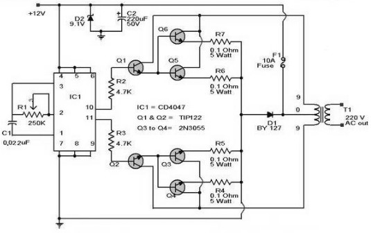
A 12 V car battery can be utilized as the 12 V input power source. The potentiometer R1 can be adjusted to achieve a 50 Hz output frequency. It is recommended to use a 10 A fuse in series...
This bell ring generator utilizes the MC14106 or 40106 hex Schmitt inverter IC to produce a dual-tone ringing sound akin to that of standard doorbell units. The circuit design of the bell ring generator is centered around the MC14106 or...
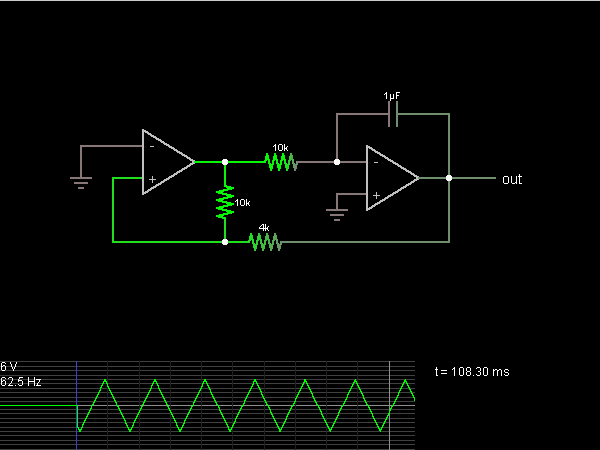
The second half of the circuit is an inverting integrator. The first operational amplifier (op-amp) begins with its two inputs in an unknown state; it can be assumed that it starts with the non-inverting input slightly higher than ground....
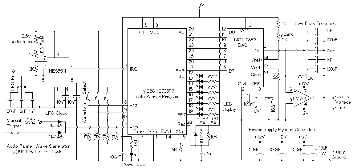
This device is a microprocessor controlled waveform generator that can be used for driving a voltage controlled stereo panner for music applications. Panning is simply the movement of a mono audio signal between the left and right channels of...
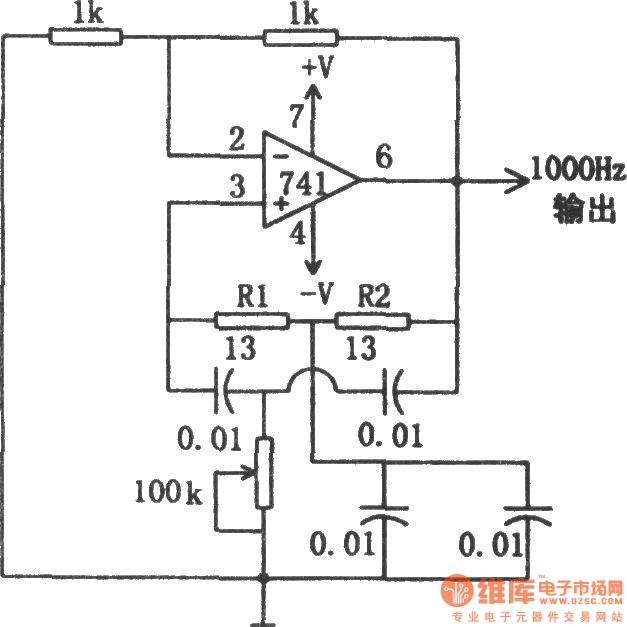
The circuit illustrated in the diagram is a 1 kHz sine wave oscillator circuit. Based on a double-T circuit configuration, it utilizes a standard 741 operational amplifier to generate a 1000 Hz sine wave output. The circuit begins oscillation...
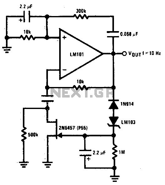
The 2N5457 JFET is utilized as a voltage variable resistor within the amplifier feedback loop, resulting in a low distortion, constant amplitude sine wave and optimizing the amplifier loop gain. The LM103 zener diode serves as the voltage reference...
Warning: include(partials/cookie-banner.php): Failed to open stream: Permission denied in /var/www/html/nextgr/view-circuit.php on line 713
Warning: include(): Failed opening 'partials/cookie-banner.php' for inclusion (include_path='.:/usr/share/php') in /var/www/html/nextgr/view-circuit.php on line 713