
basics ladder logic

A basic example of ladder programming illustrates this concept: the left vertical line represents the "power" line, and current must flow through the "butt" switch to activate the load, such as a lamp. Although a return vertical line for electricity is typically present to complete the circuit, it is omitted in this simplified diagram. If the "butt" switch is connected to a PLC's digital input and the lamp is connected to the PLC's switch output, the effect remains the same as if the switch directly controlled the lamp. However, using a PLC becomes advantageous when simplifying complex circuits.
For instance, if three switches are needed to control a light bulb, the master switch must be open while one of the control switches must be closed. This scenario is akin to a three-way switch setup in a home. All three switches can be connected to the PLC's digital inputs, and the lamp can be connected to the PLC output. A ladder program can be written to facilitate this operation. In ladder logic, a point with a "/" across its body represents a normally closed (NC) switch. An NC switch operates under negative logic; if the input is activated, the point becomes open.
In the ladder logic, if the "Master" and "controlSW1" inputs are activated while "controlSW2" is not, current flows through the "Master," "controlSW1," and the NC "controlSW2," thus activating the lamp. Conversely, if "controlSW1" is inactive and "controlSW2" is active, the lamp will also turn on because current can flow through the "Master" and then through the NC "controlSW1" and the normally open (NO) "controlSW2." If both "controlSW1" and "controlSW2" are activated simultaneously, the lamp will be turned off. Although "controlSW1" is connected to a PLC input, it may appear twice in the ladder logic. In practical PLC wiring, "controlSW1" and "controlSW2" would need to be multi-polar types with both normally open and normally closed physical points. However, when utilizing a PLC, these switches can be managed more efficiently.
This programming approach allows for enhanced control and flexibility in managing electrical loads, demonstrating the effectiveness of ladder logic in modern automation and control systems.Ladder logic programming method is a method commonly used in electrical simulation schematic control system programming languages evolved. A circuit control system but the basic purpose of the decision in some cases all the load circuit should be opened or closed.
So as to understand the ladder line, the flow of the circuit should be remembered that the concept - when the current can flow to a load, it will be opened, and when the current can not flow to a load, it will be off. The most basic element of the ladder is a " point" (). Point of only two states: open or closed. Open circuit current will not flow through the points, but closed it when the current will flow through to the next element. The simplest point of is the need to external forces (such as a human finger) can change the state of the switch.
Limit switch is placed in different positions of mobile machinery and equipment small switch, when the mechanical equipment will be moved to a location corresponding limit switch is set to open or closed state. If the point is connected to the load and the is closed, then the load will be activated. The following simple example illustrates the basic ladder programming in general: Method: As shown above, the left vertical line is the "power" line, the current must flow through the "butt" to start the load "lamp.
" (In fact, right where the load should have a vertical line to allow the return of electricity to the power process the negative side, but the reasons were to simplify the circuit diagram omitted). Now, if you are not directly to the power through the "butt" switch and then received a light load "light bulb", but rather the switch "butt" to connect to the PLC`s digital input, and will "light bulb" to connect to the PLC`s switch output, and then into the inside in the PLC ladder program, the effect would be exactly the same.
Of course, if this is the only control you want to do it is not necessary to use the PLC. Then we will see how the PLC can simplify the complex circuit. Now, for example, if it is necessary to use three switches control a light bulb. If you want to light the lamp, then a master switch "Master" must be open, and two control switches "controlsw1" and "controlsw2" One must be closed specialfn. htm # 2 while the other must be open. (Imagine your home you will be a little three-way switch concept). We can all three switches are connected to the PLC of the three digital inputs, and then load "lamp" a switch connected to the PLC output.
We can write the following ladder program to perform this operation: Figure in the point if there is a "/" across the body it is a normally closed (NC) s. NC point but negative logic, that is, if the input is activated in the absence of the point In the closed state, when it is started when the input point of but instead is open.
Therefore, in the ladder, like the "Master" and "controlSW1" input is activated, but "controlSW2 input has not been activated, current from the power flow through the" Master ", " controlSW1 ", and" controlSW2 "(since" controlSW2 " not activated, so the NC s are closed but the state) and start the "lamp". On the other hand, if the "controlSW1" has not been started, and "controlSW2" was launched, "lamp" or will be started, because the current can flow through the "Master", and then through the parallel branch lines, through the NC`s "controlSW1" and NO`s "controlSW2".
On the other hand, such as "controlSW1" and "controlSW2" was launched at the same time, that "lamp" is turned off. Note: As shown, although the "controlSW1" switches are only connected to a PLC input hardware, but it appears twice in the ladder.
But if you do not make the actual PLC electrical wiring, and that in the above circuit "controlSW1" and "controlSW2" will have to be multi-polar type and have both normally open and normally closed to the physical points. However, if you use the PLC, then the two switches are ch 🔗 External reference
Related Circuits
FM receivers are primarily of the superheterodyne type. To understand FM radio receivers, it is essential to consider the key differences between AM and FM signals. While it may seem obvious, these differences are significant. An AM receiver depends...
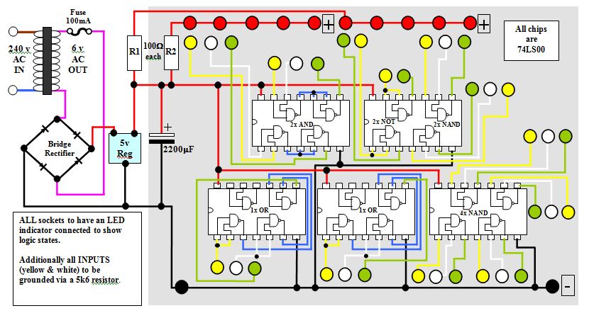
This circuit diagram for a logic tutor kit was created using MS Word graphics. While modern software is commonly utilized, there may be instances where traditional methods are necessary. Employ a sharp pencil and a ruler to ensure precision;...
The logic designer is filled with features. It would not be possible to list all the possible combinations of the unit as the various building blocks on the board can be interconnected to obtain a wide variety of counting...
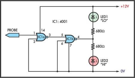
This simple logic probe has both LEDs illuminated with no signal at the input. However, due to the NOR gates connected to the probe, it indicates correctly when a high or low signal is present. It also functions correctly...
The NE556 timer IC can be utilized to create an audible indication of the static state of terminals in digital logic. An audible logic probe can be particularly beneficial when visual observation is not feasible. The NE556 timer is a...
The figure illustrates the schematic for a versatile logic probe. The zener diode clamps the input signal slightly above the TTL inverter's 2.2-V trigger voltage. Zener diode D1 can be omitted if the probe is intended solely for use...