
Bat detector frequency counter

The frequency meter circuit consists of several key components, including the microcontroller, LED display, and supporting passive components. The microcontroller serves as the central processing unit, executing the frequency measurement and display logic. The LED display consists of four 7-segment units, which require a common cathode configuration to function correctly with the microcontroller's output pins. Resistors are used to limit the current through the LEDs, ensuring they operate efficiently without exceeding their rated current. Capacitors are strategically placed across the power supply lines to filter out noise and stabilize the voltage, minimizing the effects of crosstalk from the display refresh rate.
The microcontroller is programmed to sample the input frequency by counting the number of oscillations over a defined time interval. The TMR0 timer is employed for this purpose, with a prescaler to extend the counting range. The resulting count is translated into a frequency reading that is formatted for display, taking care to eliminate leading zeros for a cleaner output. The timing of the display updates is synchronized with the counting process to ensure accurate representation of the frequency.
When designing the circuit, attention must be paid to the layout to minimize interference between components, particularly between the display and the frequency detection circuitry. Proper grounding techniques and the use of decoupling capacitors will enhance the overall performance and reliability of the frequency meter.This text describes preliminary plans for a frequency meter for a bat detector. It measures the frequency of the local oscillator in a heterodyne type bat detector. This provides a valuable tool to help identifying the bat. The frequency is displayed on four 7-segment LED displays in xxx. x kHz format, with an estimated accuracy of better than 0. 5% . Power consumption is low at approximately 7 mA at 6V. This counter can be very useful in the determination of the bat call frequency. Just tune your heterodyne bat detector to the position where the bat call sounds lowest and read the frequency from the display. It also removes the need for a calibrated frequency scale, since you can simply read the frequency and adjust for the desired frequency.
So there`s no need anymore for an ultra-stable oscillator. Using LEDs for the display has the advantage that you can read the frequency when it is dark. This also means that the light level from the LEDs can be quite low and little supply current is used. The frequency counter can be built using the popular PIC16C84 or PIC16F84 microcontrollers from Microchip.
These are quite cheap to buy; development tools are freely downloadable and a simple programmer can be built out of about 10 electrical components. I don`t have a schematic of the counter yet, but it is very similar to the schematic on the right. (link to original schematic) Significant differences between this schematic and the schematic for my bat counter are: Forget about the transistors and the resistor connected to the transistors.
They are not needed if you draw only a little current from the PIC. Connect RA0-RA3 directly to the respective common cathode connections of the LEDs. The resistor from Vdd to the /MCLR input is 10 kohm. The circuit expects a full-voltage square wave on its input, so it is best suited for bat detector that uses a square wave oscillator like a 4046 CMOS IC. The biggest problem with this circuit seems to be the crosstalk from the 100 Hz display refresh rate into the bat detector.
This can be alleviated by placing sufficiently large capacitors across the supply. I think it`s also good to keep the circuit as compact as possible. The microcontroller measures the frequency by counting the number of oscillator pulses in a 10 ms period. This value directly gives you the frequency in multiples of 100 Hz and can be put on the display. Counting the number of pulses is done with the built-in TMR0 counter and the prescaler, using a trick described in Microchip application note AN592.
During counting, the display is also updated. Each digit is lighted for 2. 5 ms by setting the appropiate common cathode pin (one of RA0-RA3) to 0 and outputting the a 7-segment code on the RB1-RB7 pins. Leading zeroes are removed so 43. 5 kHz would indeed be displayed as 43. 5 instead of 043. 5, further saving average current consumption. This is the PIC source code for use with a PIC16C84 and a common cathode display. You may need to make small changes to make it work with your particular type of processor and type of display.
You can compile it into a. HEX file with the free MPASM compiler from Microchip. Check if you use the PIC16C84 or the PIC16F84. There are a few small differences between the two processors You need to set a switch in the source-code to set the type. If you set this wrong, the microcontroller might not reset properly at start-up. Check if your display is of the common cathode or of the common anode type. Set the appropriate switch in the source code accordingly. The display probably looks very weird when you set this incorrectly. Make sure that you don`t override the default radix of 10 by a commandline parameter. If you see 55x. x on the display instead of the frequency, then this is the problem. It saves in cost and in current drain. Also the software for counting the pulses gets somewhat easier to program. Some experimental code for a two-digit counter can be found here. LEDs are probably more efficient at a current of about 7 mA than at a current of 0. 7 mA. Pulsing the LED at 7 mA with a 0. 05 duty cycle results in the same average current as multiplexing it with 0. 7 mA (considering a 2-digit display). However due to the higher efficiency, the brightness will be higher. Increasing the LED current is done by simply changing the value of the resistors in series with the LEDs.
For an approximate 7 mA current, 470 ohm resistors should be used. 🔗 External reference
Related Circuits
This document outlines a battery monitoring circuit designed to measure the voltage of 12V lead-acid batteries, such as those used in automobiles. The circuit utilizes the LM3914 integrated circuit (IC) along with several external components, including a series of...
A straightforward method for charging a battery using a higher voltage source is illustrated in the accompanying circuit diagram. The circuit requires only one resistor to establish the desired charging current, which can be determined by dividing the voltage...
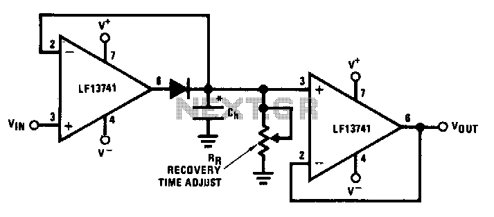
This circuit utilizes operational amplifier U1 to correct the offset in the peak detector diode D1. The voltage across capacitor C is the precise peak voltage. Additionally, U2 functions as a voltage follower to measure this voltage. The described circuit...
This is an infrared (IR) proximity detector circuit. A matched infrared emitter and detector pair is used in this circuit. The voltage-controlled oscillator is involved. The infrared proximity detector circuit utilizes a matched pair of infrared emitter and detector components...
This project measures the clock pulses supplied to the Timer input of the AVR microcontroller. The Bascom code counts the clock pulses over a duration of 1 second and displays the result. The circuit for this project primarily consists of...
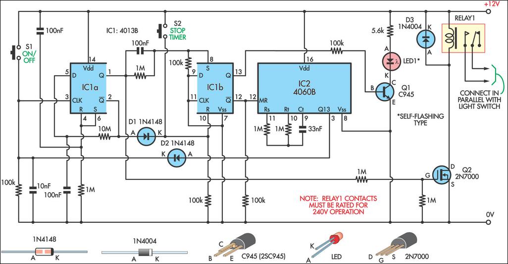
This 9-minute timer switch can be utilized to control lighting in a toilet or bathroom. The timer is activated by pressing switch S1 and deactivated by pressing S1 again. If the timer is not manually turned off, the light...