
Battery charge-discharge indicator
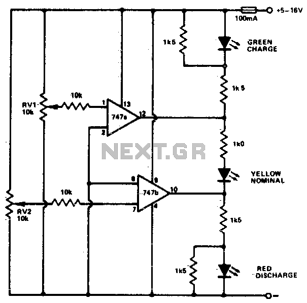
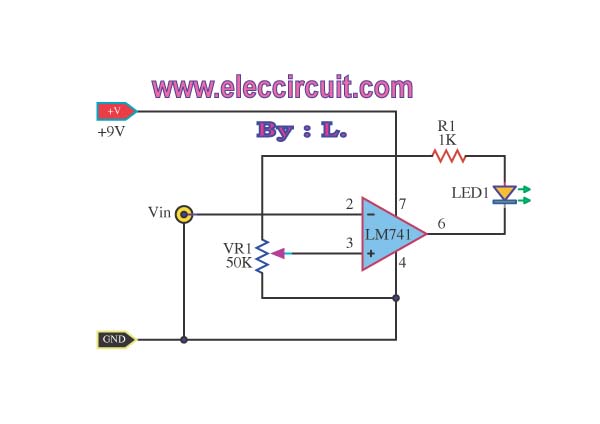
The described circuit functions as a battery voltage monitor, providing visual indicators for the operational status of a vehicle's battery. The primary components include a voltage divider network, a set of operational amplifiers (op-amps) configured as comparators, and three light-emitting diodes (LEDs) that serve as indicators.
The voltage divider, composed of resistors, scales down the battery voltage to a suitable level for the op-amps. The adjustment potentiometers RV1 and RV2 allow for fine-tuning of the voltage thresholds that determine when each LED will activate. The op-amps compare the scaled voltage against reference voltages set by additional resistors or zener diodes, which establish the precise voltage levels at which the LEDs will turn on or off.
When the battery voltage drops below 11V, the red LED will illuminate, signaling a low voltage condition. This serves as a warning to the driver that the battery may be nearing a state where it cannot start the vehicle. If the voltage rises above 12V, the green LED activates, indicating that the battery is in a healthy operating range. The yellow LED, which lights up between 11V and 12V, provides a transitional indication that the battery voltage is approaching a critical threshold.
This circuit can be implemented on a printed circuit board (PCB) for durability and reliability. It is essential to ensure that the components are rated for the automotive environment, which can include exposure to vibrations, temperature variations, and moisture. Proper layout and grounding techniques should be employed to minimize noise and ensure accurate voltage readings.This circuit monitors car battery voltage. It provides an indication of nominal supply voltage as well as low or high voltage. RV1 and RV2 adjust the point at which the red/yellow and yellow/green LEDs are on or off. For example the red LED comes on at 11V, and the green LED at 12V The yellow LED is on between these values. 🔗 External reference
Related Circuits
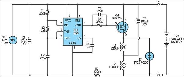
Almost all 24V power systems in trucks, 4WDs, RVs, boats, etc., utilize two series-connected 12V lead-acid batteries. The charging system can only sustain the total voltage of the individual batteries. If one battery is failing, this circuit will illuminate...
The modem off indicator is designed specifically for avid Internet users. It is evident that the circuit for this indicator is quite simple. The modem off indicator serves a crucial function for users who rely heavily on internet connectivity. This...
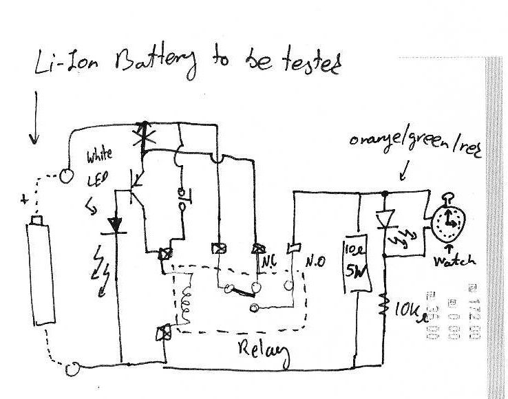
It is assumed that individuals interested in constructing this circuit can interpret the schematics provided below. Basic principles: Note that lithium-ion batteries should not be discharged below 3V. The circuit design focuses on the safe operation of lithium-ion batteries, particularly...
With this circuit can determine whether any of the phones of the same line is busy (it's up the handset), with the help of a LED. The circuit has no measurable effect on the telephone, so that there are...
The following circuit illustrates a 6/12/24V Lead Acid Battery Charger Circuit Diagram. Features: It is essentially a high-voltage pulse generator. The circuit diagram for a 6/12/24V Lead Acid Battery Charger is designed to efficiently charge lead-acid batteries of varying voltages....
This simple low voltage tester circuit can be used to monitor batteries and other voltage sources for issues, utilizing an LED display and alarm sound. The low voltage tester circuit is designed to provide a reliable method for monitoring the...