
Emergency Telephone Dialer Circuit

The electronic schematic for this alert system consists of several key components: a sensor switch, a microcontroller, a telephone dialing module, and a panic switch. The sensor switch can be either open-loop or closed-loop, depending on the specific application and installation requirements.
When the sensor switch is triggered, it sends a signal to the microcontroller, which is programmed to initiate the dialing sequence. The microcontroller is responsible for storing the programmed phone number and controlling the dialing module. The dialing module interfaces with the telephone line and is capable of generating the necessary tones for dialing and signaling.
In addition to the primary alert function, the panic switch serves as an emergency trigger that can be activated by an individual in distress. This switch can be a simple momentary push button that, when pressed, sends a signal to the microcontroller to initiate a call to a pre-set emergency contact.
The circuit includes a power supply that can be connected to a standard AC outlet or powered by a battery backup to ensure functionality during power outages. Proper circuit protection should be implemented, including fuses and surge protectors, to safeguard the components from voltage spikes and other electrical anomalies.
Overall, this alert system provides a robust solution for monitoring and responding to emergencies, ensuring that help can be summoned quickly and efficiently. The design can be further enhanced with additional features such as SMS notifications, remote monitoring capabilities, and integration with home automation systems, depending on the specific needs of the user. This system will alert you or anyone chosen by automatically dialing a programmed phone number. This is accomplished by monitoring an open- loop or closed-loop sensor switch located in the protected area. Mien the sensor detects a problem (such as a break-in, fire, heating system failure, flood, etc.), Teleguard dials whatever telephone number has been programmed into its memory.
When the phone is taken off the hook, Teleguard emits an unusual tone to alert the party on the receiving end that something is amiss. The circuit is not hampered by busy signals when a call is placed; it automatically redials the number again and again (about once a minute) until it gets through. In addition, Teleguard can also automatically dial a number in the event of a medical emergency; for instance, where a mobility-impaired person is unable to dial the telephone. That can be accomplished by adding a panic switch to the circuit.
Related Circuits

This circuit utilizes a single potentiometer to control a frequency range from 300 Hz to 3000 Hz. A FET operational amplifier is employed at stages A1 and A2. The upper frequency limit is dictated by the gain-bandwidth product of...
This is a classic design of a 35 W final amplifier utilizing two EL34 tubes in a push-pull configuration, developed by Siemens and Halske. The design dates back to March 24, 1953, and is identified by the code SV410/1....

A long-duration timer can be easily constructed using a 4060 CMOS binary divider along with its integrated clock oscillator. The solid-state relay can be selected based on the specific application requirements and may be substituted with a mechanical relay...
This 555 timer circuit activates a relay upon pressing a button. The threshold and trigger inputs, pins 2 and 6, are maintained at half the supply voltage by two 10K resistors. When the output is high, a capacitor charges...
This is a simple, programmable, autonomous and extensible LED matrix with the possibility of being controlled by a computer using a RS232 connection. Its basic modules are the Controller Board, the I/O Port expander boards and the LED matrix...
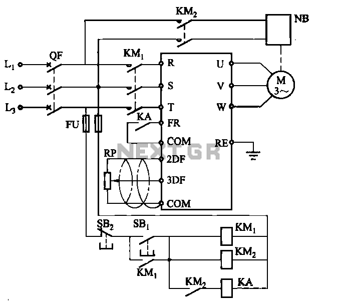
Electromagnetic brake motors consist of a motor and an electromagnetic brake, forming a standard assembly. The circuit diagram is provided. In this configuration, FR represents the forward run and stop command terminal, while the intermediate relay KA is employed...