
555 the DC capacitor tester

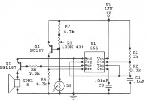
The DC capacitor tester circuit operates by generating a pulse signal through the pulse generator, which is then fed into a single-shot circuit. This circuit is designed to produce a single output pulse in response to the input pulse, effectively allowing for a controlled measurement of the capacitor's characteristics. The head indicating DC amplifier circuit is responsible for amplifying the voltage signal generated by the capacitor under test, enabling accurate readings of its capacitance.
The measurement ranges are defined by the selection of appropriate resistors and capacitors in the circuit, which determine the sensitivity and scale of the measurements. For instance, the lower ranges (0 to 100 pF and 0 to 1 nF) utilize high-precision components to ensure accurate readings of small capacitances, while the higher ranges (0 to 1 μF and 0 to 10 μF) can accommodate larger capacitors, making the tester versatile for various applications.
In practical use, the tester is connected across the terminals of the capacitor to be measured. The resulting voltage signal, once amplified, can be displayed on a digital or analog meter, providing a clear indication of the capacitor's value. This circuit is particularly useful in electronics testing and repair where accurate capacitance measurements are necessary for troubleshooting and component validation. As shown in Figure 555 constituting the DC capacitor tester. The tester from the pulse generator, single-shot, and the head indicating DC amplifier circuit. It measures NpF ~ 1 0 mu F capacitor. Range is divided into 0 ~ 100PF, 0 ~ 1nF, 0 ~ 10nF, 0 ~ 100nF, 0 ~ 1 mu F, 0 ~ 10 mu F.
Related Circuits
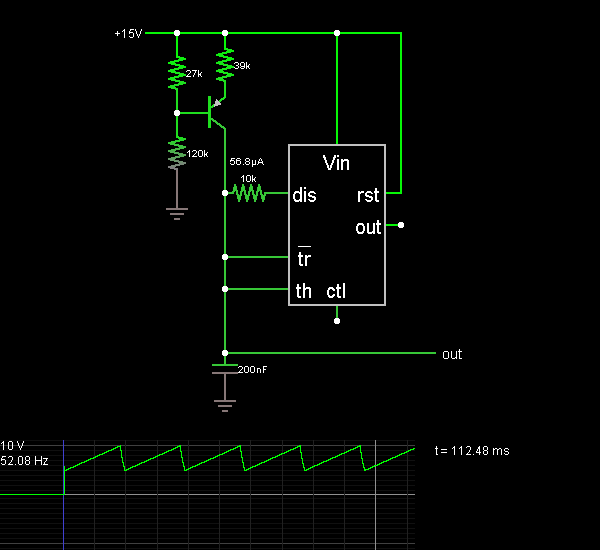
This document presents the 555 Sawtooth Oscillator circuit diagram along with a detailed explanation of its operational principles. An electronic circuit simulator is available to assist in designing the 555 Sawtooth Oscillator circuit and simulating it online for enhanced...
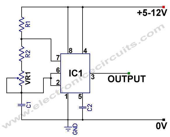
555 Variable Frequency Square Wave Generator. This simple 555 Variable Frequency Square Wave Generator produces a variable frequency output. The 555 Variable Frequency Square Wave Generator is a versatile circuit that utilizes the 555 timer IC to generate square wave...
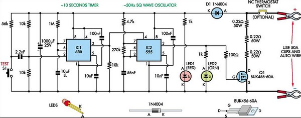
This circuit is designed to check the condition of lead-acid and gel cell batteries with capacities greater than 20Ah. It switches a load of about 18A at a rate close to 50Hz so that the internal resistance of the...
The following circuit illustrates a Sun Up Alarm Light Alarm Circuit Diagram. This circuit is based on the 555 Integrated Circuit (IC). Features include simplicity and cost-effectiveness. The Sun Up Alarm Light Alarm Circuit employs the 555 timer IC in...

The 555 timer IC is an integrated circuit used in various timer, pulse generation, and oscillator applications. Its continued popularity is attributed to its ease of use, low cost, and good stability, with an estimated production of 1 billion...
The LMV116 is an enhanced slew rate version of the LMH6645. The high-speed LMH devices are very sensitive to output capacitance (typically designed to drive back-terminated loads) and can begin to oscillate with direct capacitive loads as low as...