
fun electronic circuits

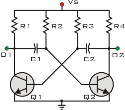
The circuit utilizes two astable multivibrators to create a visually dynamic LED display. Each multivibrator operates independently, generating square wave outputs that drive the LEDs. The transistors T1 and T2 form the first multivibrator, where the timing components (resistors and capacitors) dictate the oscillation frequency. The second multivibrator, made up of transistors T3 and T4, operates under similar principles.
The RC time constant, which is critical in determining the frequency and duty cycle of the output signals, can be adjusted using the potentiometers VR1 and VR2. This feature allows for fine-tuning of the LED flashing rates and patterns, providing a customizable user experience. By varying the resistance of these potentiometers, the charging and discharging times of the capacitors can be changed, thus altering the frequency of the output pulses.
In an alternative configuration, using light-dependent resistors (LDRs) instead of potentiometers introduces a reactive element, allowing the circuit to adapt its performance based on ambient lighting conditions. This modification creates a more interactive display, where the speed and pattern of the LED flashing respond dynamically to changes in light intensity.
The design's simplicity, along with its low cost, makes it an accessible project for hobbyists and educators alike. The circuit can be easily constructed on a breadboard or printed circuit board (PCB), and the arrangement of colored LEDs can be customized to enhance visual appeal, making it suitable for various applications such as decorative lighting, indicators, or educational demonstrations in electronics.Here is a simple circuit which can be used for decoration purposes or as an indicator. Flashing or dancing speed of LEDs can be adjusted and various dancing patterns of lights can be formed. The circuit consists of two astable multivibrators. One multivibrator is formed by transistors T1 and T2 while the other astable multivibrator is formed by T3
and T4. Duty cycle of each multivibrator can be varied by changing RC time constant. This can be done through potentiometers VR1 and VR2 to produce different dancing pattern of LEDs. Total cost of this circuit is of the order of Rs 30 only. Potentiometers can be replaced by light dependent resistors so that dancing of LEDs will depend upon the surrounding light intensity. The colour LEDs may be arranged as shown in the Figure 🔗 External reference
Related Circuits
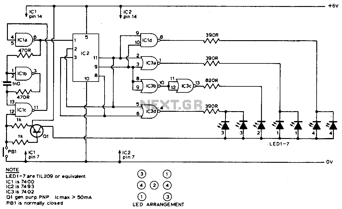
Six LEDs are arranged to create a display that mimics the dots on a dice. When the push button input (PBI) is pressed, the display is turned off, and the oscillator (IC1 a, b, c) drives IC2 at approximately...
This circuit is designed to drive a relay coil using a low power output, typically from an integrated circuit (IC) such as a 555 timer or a TTL/CMOS device. It facilitates the switching of high loads or loads requiring...
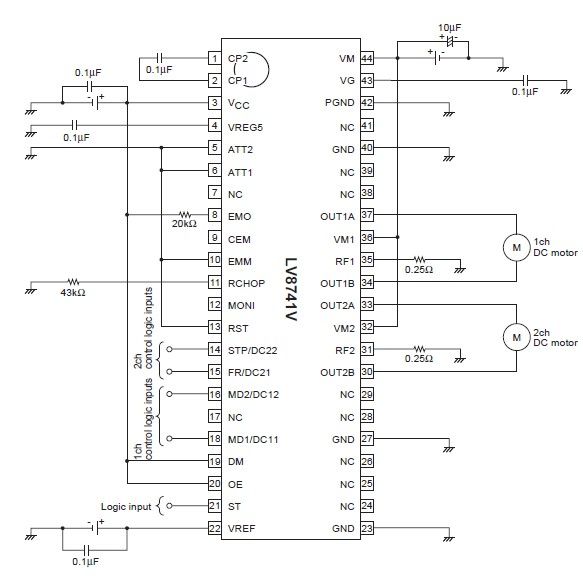
The circuit diagram illustrates an electronic project that requires a few external electronic components. The PWM current-control stepping motor driver IC can provide a maximum output current of up to 1.5 amperes. The configuration settings for the PWM current-control...
Basic information on the construction of various types of lasers from scratch, including topics such as home-built laser safety, setting up a home laser lab, sources of supplies and chemicals, vacuum systems, glass working, structural materials, power supplies, and...
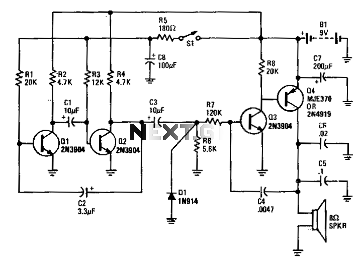
Transistors Q1 and Q2 form the two halves of a free-running multivibrator, with the frequency determined by the voltage across capacitor C8. This capacitor is charged and discharged by the operation of switch S1. Transistors Q3 and Q4 constitute...

This electronic circuit, based on the CD4017 and logic gates, activates a relay when four keys are pressed in the correct sequence, returning to the initial state afterward. The circuit utilizes the CD4017 decade counter, which is designed to count...