
BF495 Transistor For Am Transmitter Radio

The BF495 transistor is a high-frequency NPN transistor commonly used in RF applications, including AM transmitters. In this circuit, the BF495 is employed to amplify the audio signal before modulation. The circuit typically consists of several key components: the BF495 transistor, a power supply, an audio input source, and an antenna.
The operation begins with the audio input, which is fed into the base of the BF495 transistor. As the audio signal varies, it modulates the current flowing through the transistor, which is configured in a common-emitter configuration to achieve amplification. The collector of the transistor is connected to a tuned circuit, which consists of an inductor and capacitor that resonate at the desired AM frequency. This tuned circuit is crucial as it allows the circuit to transmit signals effectively over the airwaves.
The output from the collector is then coupled to an antenna, which radiates the modulated signal. The use of ceramic components in the circuit enhances stability and reduces losses, contributing to the overall efficiency of the transmitter. The circuit may also include additional components such as resistors and capacitors for biasing and filtering purposes, ensuring optimal performance.
In summary, the BF495 transistor circuit provides a robust solution for AM transmission, leveraging the characteristics of the transistor and the design of the tuned circuit to achieve effective signal broadcasting.This circuit shows about BF495 Transistor For Am Transmitter Radio Circuit Diagram. Features: powerful AM transmitter, using ceramic .. 🔗 External reference
Related Circuits
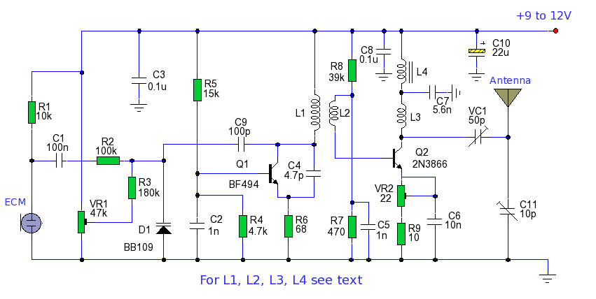
The power output of many transmitter circuits is low due to the absence of power amplifier stages. The transmitter circuit presented here includes an additional RF power amplifier stage after the oscillator stage, which elevates the power output to...
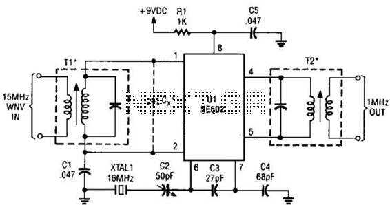
This simple frequency converter mixes the 15-MHz WWV/WVH signal with a 16-MHz signal from the local oscillator (LO) to convert it down to 1 MHz, enabling it to be received on an AM-band receiver. The frequency converter operates by utilizing...

This circuit is designed to generate audio musical notes that can be heard from a distance of up to 10 meters. The circuit consists of two main components: an infrared (IR) music transmitter and an IR music receiver. The...
The core component of the circuit is a Colpitts type oscillator. The capacitors C3, C4, C5, C6, diodes CD1-CD2, and inductor L1 determine the oscillation frequency. The active components in the oscillator include the BF982 and a dual-gate MOSFET....
The following plans outline the construction of a compact tracking transmitter that can be detected using an FM broadcast band radio receiver. The transmitter operates on a battery voltage range of 3 volts to 9 volts and has a...
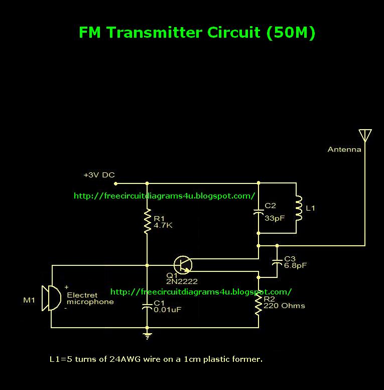
This is an FM transmitter circuit diagram. This circuit uses a 2N2222 transistor, allowing it to operate at 3V and transmit signals up to 50 meters. The FM transmitter circuit consists of several key components, primarily centered around the 2N2222...