
Undervoltage indicator for battery equipment

The circuit utilizes an NE555 timer configured in a monostable mode to monitor a specific voltage level. The primary function of this circuit is to illuminate an LED when the voltage drops to a predetermined threshold, specifically 12 volts. The low duty cycle of the flashing LED ensures minimal average current consumption, maintaining it at or below 1 mA. This is particularly beneficial in battery-operated devices where power efficiency is critical.
To achieve the desired voltage monitoring capability, resistors R1 and R2 are utilized to set the reference voltage at which the NE555 triggers the LED. The relationship between R1 and R2 determines the threshold voltage. By adjusting the values of these resistors, the voltage level at which the LED activates can be precisely controlled. This flexibility allows for customization based on different application requirements.
The NE555 timer operates by charging and discharging a capacitor connected to its timing pins, which in turn influences the output state that drives the LED. When the monitored voltage falls to 12 volts, the voltage divider formed by R1 and R2 provides a sufficient voltage to the trigger input of the NE555, causing it to switch the output high, thus turning on the LED.
This circuit design is particularly effective for applications requiring voltage level monitoring, such as battery management systems, where visual indicators for low voltage conditions are necessary. The simplicity of the NE555 timer combined with the adjustable resistor configuration makes this design both practical and efficient for various electronic projects.Due to the low duty cycle of flashing LED, the average current drain is 1 mA or less. The NE555 will trigger the LED on when the monitored voltage falls to 12 volts The ratio of Rl to R2 only needs to he changed if it is desired to change the voltage point at which the LED is triggered.
Related Circuits
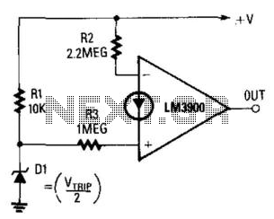
The output becomes high when the supply voltage drops below a threshold set by the zener diode D1. If D1 is a 5.6-V zener diode, the operational amplifier will activate when the supply voltage decreases to around 11 V....
A simple NiCd charger can be constructed using commonly available components and an inexpensive LM317 or 78xx voltage regulator. The design incorporates a current limiter composed of resistor R3 and a transistor, allowing it to charge multiple cells until...
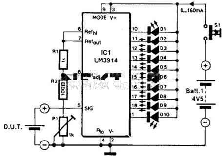
The LM3914A bar graph LED is utilized as a voltmeter for testing batteries. This circuit operates on a 4.5-V battery and compares the battery under test with an internally generated reference, established by resistors R1, R2, and potentiometer P1....
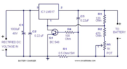
A simple lead-acid battery charger circuit with a diagram and schematic using the IC LM317, which provides the correct battery charging voltage. This lead-acid battery charger should be supplied with an input of 18 volts to the IC. The lead-acid...

This is a simple yet effective charger for lead-acid batteries. It utilizes a 12-volt car bulb as both a current regulator and a charge status indicator. The described circuit is an innovative approach to charging lead-acid batteries. It employs...
Here is a circuit for using the printer port of a PC for control application using software and some interface hardware. The interface circuit along with the given software can be used with the printer port of any PC...