
build an illuminated hi end digital clock

The digital clock circuit utilizes the MM5402 clock IC, which serves as the primary timekeeping component. This integrated circuit is designed to provide accurate timekeeping and is capable of driving a 7-segment LED display to show hours and minutes. The MM5369 clock generator IC complements the MM5402 by generating the necessary clock signals, ensuring synchronization and precision in time display.
The circuit design includes several additional components to enhance functionality. A potentiometer can be integrated to allow for slow/fast time adjustments, enabling users to calibrate the clock as needed. The sleep timer feature can be implemented using a simple timer circuit, which can be triggered by a button press, allowing the clock to enter a low-power mode after a specified duration.
For the alarm function, a piezo buzzer can be connected to the output of the MM5402. The alarm can be set by using additional switches that allow users to program the desired wake-up time. The snooze feature can be achieved by incorporating a momentary push button that temporarily silences the alarm for a preset duration before it sounds again.
Battery backup is crucial for maintaining timekeeping during power outages. A rechargeable lithium-ion battery can be used in conjunction with a charging circuit to ensure that the clock continues to function even when disconnected from mains power. A diode can be added to prevent reverse current from the battery, ensuring that the circuit remains safe and functional.
The complete circuit diagram should clearly illustrate the connections between the MM5402, MM5369, and the supporting components, including the display, buttons for setting the time and alarm, and the battery backup system. Proper labeling of each component will facilitate easier assembly and troubleshooting for individuals looking to replicate this digital clock design.Making a hi-end, accurate digital LED clock today is as easy as cooking noodles. The article explains how a digital clock can be made using over the counter electronic chips like the National s MM5402 clock IC and a handful of other components. This single chip along with a clock generator IC MM5369 together provides some outstanding features other than the usual time displays.
Features like slow/fast time setting, sleep timer, alarm with snooze and battery back-up are all included in this proposed circuit of a digital clock. Complete circuit diagram is enclosed herein.. 🔗 External reference
Related Circuits
This circuit is a small +5V power supply, which is useful when experimenting with digital electronics. Small inexpensive wall transformers with variable output voltage are available from any electronics shop and supermarket. Those transformers are easily available, but usually...
The digital lock shown below uses 4 common logic ICs to allow controlling a relay by entering a 4 digit number on a keypad. The first 4 outputs from the CD4017 decade counter (pins 3,2,4,7) are gated together with...
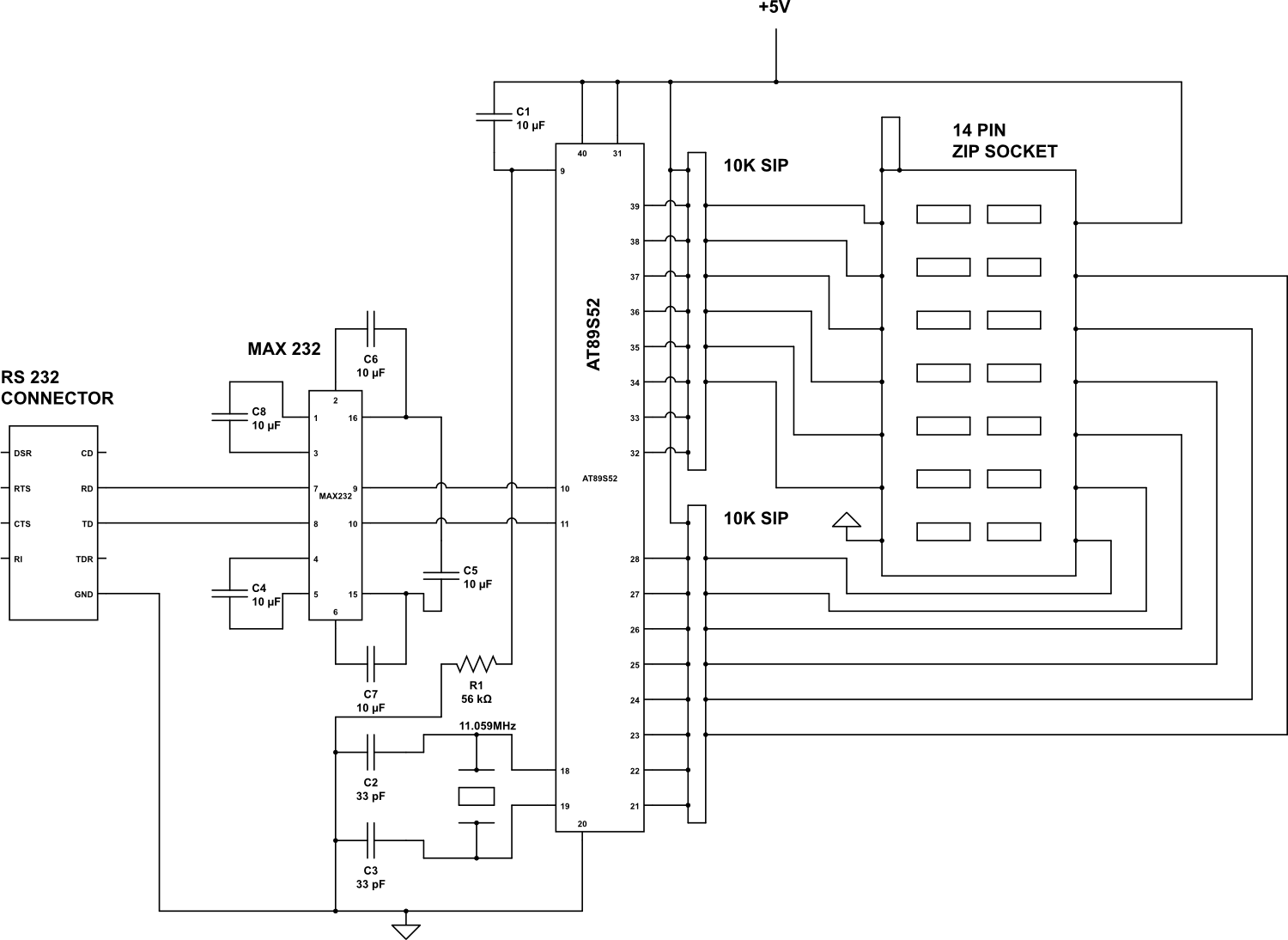
Check the following ICs: 7400, 7402, 7404, 7408, 7432, 7486. A Visual Basic program is utilized to display the results on the PC. The microcontroller AT89S52 receives the IC number from the PC, verifies the logic gates with the...
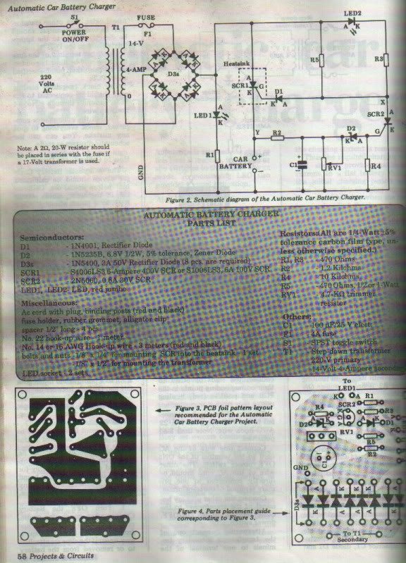
This project is designed for individuals interested in constructing their own Automatic Battery Charger. It has been developed by duc_tech. The Automatic Battery Charger project involves creating a circuit that can efficiently charge batteries without requiring constant supervision. The design...
The above shows a home-built digital clock that utilizes Nixie tubes for display. Unlike most contemporary Nixie clocks, this design does not employ transistors or integrated circuits for driving the tubes. Instead, the driving logic is constructed using neon...

A digital tachometer and speedometer utilizing a seven-segment display was initially attempted but not successfully implemented due to overcrowding of integrated circuits (ICs) and components. An LED tachometer was successfully constructed later, followed by the development of an LED...