
Call Acknowledged !

This circuit is designed for effective communication in environments where noise levels are high, and it employs a straightforward yet efficient method to notify individuals of incoming calls. The use of a two-transistor multivibrator allows for the generation of a pulsed signal, which is crucial for ensuring that alerts are noticeable amid ambient noise. The selection of components is based on their voltage characteristics, optimizing the performance of the LEDs and buzzer. The red LED acts as a visual alert for the sender, while the buzzer provides an auditory signal, making it suitable for various applications, including home and office settings.
The simplicity of the two-wire connection enhances the circuit's versatility, allowing for easy installation without the need for complex wiring or additional infrastructure. The acknowledgment feature, facilitated by switch S2, provides feedback to the caller, ensuring that communication is clear and effective. The option to substitute the blue LED with other colors, combined with the diode to adjust voltage levels, enhances the circuit's adaptability to different user preferences and component availability.
Overall, this circuit is a practical solution for discreet communication, combining visual and auditory alerts to ensure that messages are conveyed and acknowledged efficiently. Its low power requirements and ease of use make it an ideal choice for domestic and professional environments where traditional intercom systems may be impractical.This circuit could be used (depending on your circumstances) by a gentleman to summon his butler, a manager his secretary or as in the author`s case to call the kids down to dinner without having to shout above the level of the CD player/TV/games console in their bedroom. Rather than resorting to a full-blown intercom system, a simpler solution wa s envisaged and while a buzzer could easily fulfil this function, this circuit has the advantage of providing a visual indication of a call as well as confirming to the caller that the message` has been received. This is especially useful in the latter case, as the call may be easily drowned out by the music playing in the headphones.
The circuit, which requires no complicated switching, uses a simple two-wire connection between the two stations and utilises the fact that the forward voltage drop of a blue (or white) LED is greater than that of a red, green or yellow one. The circuit is based on a two-transistor multivibrator which is used to pulse a red LED (D3) as well as the buzzer Bz1 on and off at about 1.
5 Hz when push button S1 is closed. This frequency may of course be altered if required by changing the values of the capacitors. The diode D1 in series with the collector of transistor T2 is required to isolate the output from the effects of the buzzer circuitry, which would alter the multivibrator frequency. In principle, the multivibrator could be dispensed with but a pulsed buzzer/flashing led is much more noticeable than a continuous signal especially in noisy conditions.
Since the voltage across a red LED is typically about 1. 5 V while a blue LED requires at least 2. 5 V to 3 V to light, the blue LED will remain off when the call button S1 is pressed. Despite being rated for operation at 3-12 V, most piezo sounders can still produce a piercing sound from the pulsed 1. 5-V available across the red LED which should get the attention of even the most preoccupied teenager.
When the recipient presses the acknowledge (push to break) switch S2, the red LED/buzzer are disconnected allowing the blue LED to flash at the sending station indicating to the caller that his call has been received. Alternatively, if a blue LED is not available, a red or green type in series with a forward biased silicon diode to raise its forward voltage above that of the red LED in the receiver could be used instead.
The circuit may be powered by a 9-V battery, a mains power supply being unnecessary in view of the low power consumption and infrequency of use of the circuit. 🔗 External reference
Related Circuits

The DC voltage on a telephone line typically ranges from 45 to 50 V when on-hook and drops to around 6 V when off-hook. This circuit utilizes the voltage drop to activate a relay, which in turn controls a...
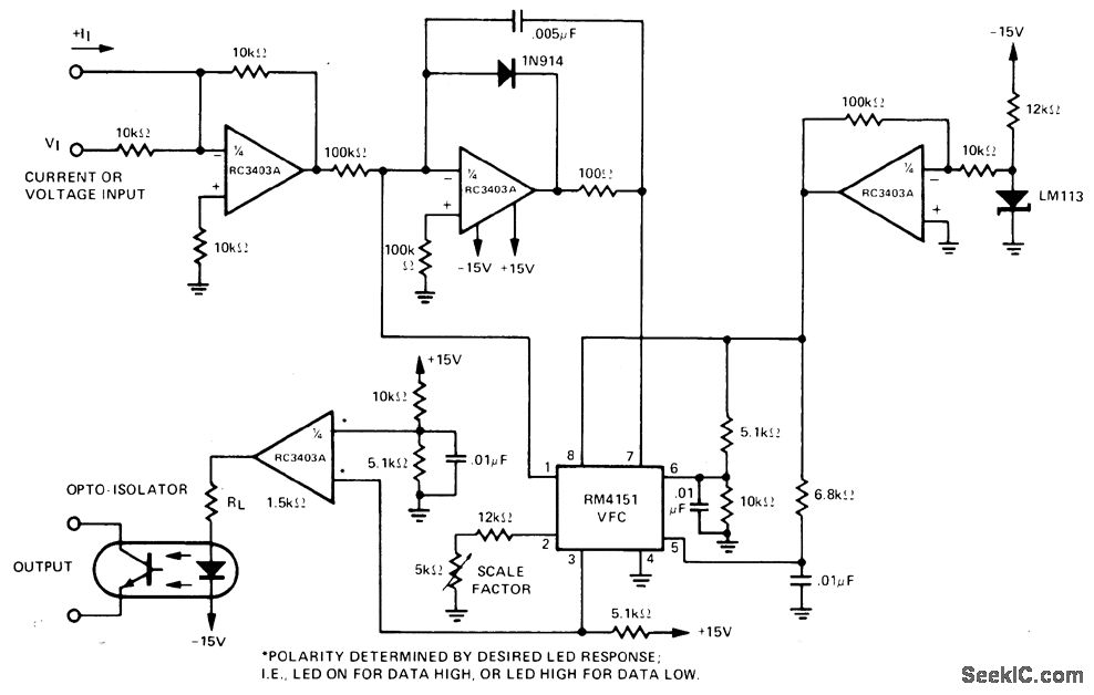
The input voltage range of 0-10 V is converted to a proportional frequency at the output of an optoisolator using the RM4151 converter. This converter is paired with the RC3403A quad op-amp, which serves multiple functions including inverter, integrator,...

LEDs are increasingly utilized in motor vehicles, replacing traditional incandescent lamps due to their superior energy efficiency and extended lifespan. This article outlines a straightforward LED tail light specifically designed for motorcycles, scooters, and mopeds. There is a notable...

The CMOS 4060 integrated circuit (IC) features two built-in inverters located at pins 9, 10, and 11, which must be interconnected to create an oscillator. The output of this oscillator is available at Pin 9, which continuously alternates between...

The application circuit operates the device as illustrated below, allowing for intermittent lighting in specific situations (e.g., during surgery). It utilizes an LCE module for blackout emergency lighting, which activates automatically after a power failure, ensuring uninterrupted illumination. In...

This circuit helps to avoid the annoyance of mobile phone rings while at home. It provides a visual indication when placed near a mobile phone, even if the ringer is turned off. When a call is received, the transmitter...