
Capacitance meter

The described circuit utilizes a charge pump configuration to measure capacitance values by translating them into a corresponding output voltage. The charge pump's pin 2 is designated for connecting the capacitor under test, while the output voltage reflects the capacitance value based on a defined relationship. Specifically, as the capacitance increases from 0.1 µF to 0 µF, the output voltage decreases linearly from 1 volt to 0 volts, indicating a direct correlation between capacitance and output voltage.
The circuit is powered by a stable 15-volt power supply, which is essential for maintaining consistent operation across the measurement range. The reference frequency of 60 Hz is critical as it provides a stable timing signal for the charge pump operation, ensuring accurate capacitance measurements. This frequency is typically derived from the mains power supply, which is common in many electronic measurement devices.
The use of a 111 kΩ resistor in the circuit serves as a part of the voltage divider or feedback mechanism, which helps in calibrating the output voltage according to the capacitance range. This resistor value is chosen to optimize the sensitivity and linearity of the output voltage in relation to the capacitance being measured.
Overall, this capacitance measurement circuit is designed for simplicity and effectiveness, making it suitable for various applications in electronics where capacitance needs to be evaluated. Proper implementation of the charge pump and associated components will yield reliable measurements across the specified capacitance range.Output voltage is proportional to the capacitance connected to pin 2 of the charge pump. The meter works over a range of 01 to 0 µF with a set at 111 K. Over this range of capacitance, the output voltage varies from 1 to 0 volts with a 15 volt power supply A constant frequency reference is taken from the 60-Hz line.
Related Circuits
The ADXL362 is an ultra-low power, 3-axis MEMS accelerometer that consumes less than 2 µA at a 100 Hz output data rate and 270 nA when in motion-triggered wake-up mode. Unlike accelerometers that utilize power duty cycling to achieve...
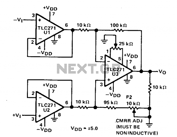
Three operational amplifiers U1, U2, and U3 are configured in a basic instrumentation amplifier arrangement. Operating from ±5 V, pin 8 of each op amp is directly connected to ground, facilitating the desired AC performance for this application (high...
This is a simple 3-digit digital voltmeter. A PIC16F676 microcontroller is utilized to read analog signals (voltage) and display the value on a 3-digit 7-segment display. Similar principles can be applied to measure DC current using a parallel resistor...
This document describes a simple 2.4 GHz SWR meter that utilizes surplus microwave hardware. The main component is a MECA -20/-20 dB Directional Coupler, which operates within a frequency range of approximately 700 MHz to 2.5 GHz. This directional...
Since I have provided the schematic for John L Linsley-Hood's Class-A amplifier, I felt that some readers may wish to experiment with the concept. Unfortunately, a very low ripple power supply is needed for all Class-A amps, and the...
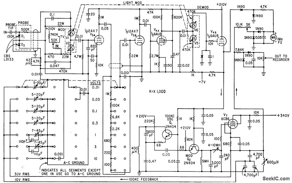
The circuit generates a low-frequency waveform with an amplitude that corresponds to an unknown RF voltage, utilizing a photochopper modulator (VI-V2) as an error detector. This arrangement provides seven voltage ranges from 10 mV RMS to 10 V RMS...