The 555 timer IC serves as the core component of the circuit, tasked with charging an unknown capacitor (Cx) to a predetermined voltage. Following this, the capacitor discharges into a meter circuit, which measures the current flowing through a 47-ohm resistor. This process is repeated multiple times per second, ensuring that the meter needle remains stable. The deflection on the meter correlates directly with the unknown capacitor's value, allowing for a linear scale similar to the voltage and current ranges found in an analog multimeter. The capacitance meter features five ranges, from 100 pF to 1 µF, selectable via a five-position, two-pole switch. Additionally, there is a x10 switch for measuring higher capacitance values and a divide-by-two function to enhance meter readability for capacitors just above 100 pF, 1,000 pF, 0.01 µF, 0.1 µF, or 1 µF. Component values are crucial for accuracy; therefore, it is recommended that the nine resistors connected to the range switch have a tolerance of 2%. If 0A47 diodes are unavailable, alternatives such as OA91 or OA95 germanium diodes may be used. The meter should be housed in a plastic enclosure, ideally similar in size to a multimeter but deeper. The meter movement should be as large as the budget permits, as it will be used for precise value indication. For example, a 70 mm diameter movement salvaged from electronic equipment was utilized in the prototype. The purchased meter will typically have a scale of 0 to 50 microamps, which needs to be modified to read 0 to 100 (i.e., 20, 40, 60, 80, 100 instead of 10, 20, 30, 40, 50) using white correction fluid or small paper pieces. Components can be mounted on matrix board or printed circuit board, and it is advisable to use a socket for the IC for future replacement needs. Short wires should be employed to minimize stray capacitance, which can compromise accuracy. Calibration of the finished meter can be performed using a pre-built capacitance meter or a selection of known-value capacitors measured with a laboratory meter. If neither option is available, purchasing several capacitors of the same value and using the one closest to the average as a reference is recommended. Multiple standards should be used to verify accuracy across all ranges. Calibration involves disabling both the x10 and divide-by-two functions (i.e., both switches open), connecting a reference capacitor, and adjusting the 47 kΩ trimpot until the meter reads the exact capacitor value. The divide-by-two function is then activated, and the 10 kΩ trimpot is adjusted to ensure the meter displays exactly twice the original reading. For instance, if a 0.01 µF reference capacitor results in a reading of 10 on the 0.1 µF range, the meter should now read 20. After switching out the divide-by-two function, the reference capacitor should match one of the available ranges (e.g., 1,000 pF, 0.01 µF, 0.1 µF, etc.), ensuring the meter reads full scale (100) for that measurement. Activating the x10 function should significantly reduce the meter indication, and the 470 Ω trimpot should be adjusted to achieve a reading of 10. When moving down one range (e.g., from 0.01 µF to 1,000 pF), the meter should again read 100, and if it does not, the 470 Ω trimpot should be varied until it does. This concludes the calibration process for the capacitance meter, which can then be used to measure other components to confirm reasonable accuracy in measurements.The common 555 timer IC forms the heart of the circuit. Its function is to charge the unknown capacitor (Cx) to a fixed voltage. The capacitor is then discharged into the meter circuit. The meter measures the current being drawn through the 47 ohm resistor. The 555 repeats the process several times a second, so that the meter needle remains steady . The deflection on the meter is directly proportional to the value of the unknown capacitor. This means that the scale is linear, like the voltage and current ranges on an analogue multimeter. The capacitance meter has five ranges, from 100pF to 1uF, selected by a five position two pole switch. In addition, there is a x10 switch for measuring higher values and a divide-by-two facility to allow a better indication on the meter where the capacitor being measured is just above 100, 1000pF, 0.
01, 0. 1 or 1 uF. Component values are critical. For best accuracy, it is desirable that the nine resistors wired to the Range switch have a 2% tolerance. If 0A47 diodes are not available, try OA91 or OA95 germanium diodes instead. Construct the meter in a plastic box; one that is about the size of your multimeter but deeper is ideal.
The meter movement should as large as your budget allows; you will be using it to indicate exact values. A round 70mm-diameter movement salvaged from a piece of electronic equipment was used in the prototype.
The meter you buy will have a scale of 0 to 50 microamps. This scale needs to be converted to read 0 to 100 (ie 20, 40, 60, 80, 100 instead of 10, 20, 30, 40, 50). Use of white correction fluid or small pieces of paper will help here. The components can be mounted on a piece of matrix board or printed circuit board. Use a socket for the IC should replacement ever be needed. Keep wires short to minimise stray capacitance; stray capacitance reduces accuracy. Calibrating the completed meter can be done in conjunction with a ready-built capacitance meter. Failing this, a selection of capacitors of known value, as measured on a laboratory meter, could be used.
If neither of these options are available, simply buy several capacitors of the same value and use the one which is nearest the average as your standard reference. Use several standards to verify accuracy on all ranges. To calibrate, disable both the x10 and divide-by-two functions (ie both switches open). Then connect one of your reference capacitors and switch to an appropriate range. Vary the setting of the 47k trimpot until the meter is reading the exact value of the capacitor. Then switch in the divide-by-two function. This should change the reading on the meter. Adjust the 10k trimpot so that the needle shows exactly twice the original reading. For example, if you used a 0. 01 uF reference, and the meter read 10 on the 0. 1 uF range, it should now read 20. Now switch out the divide-by-two function. If you are not doing so already, change to a reference with a value equal to one of the ranges (eg 1000pF, 0.
01uF, 0. 1uF etc). Switch to the range equal to that value (ie the meter reads full-scale (100) when that capacitor is being measured. Switching in the x10 function should cause the meter indication to drop significantly. Adjust the 470 ohm trimpot so that the meter reads 10. Move down one range (eg from 0. 01uF to 1000pF). The meter should read 100 again. If it does not, vary the 470 ohm trimpot until it does. That completes the calibration of the capacitance meter. Now try measuring other components to confirm that the measurements are reasonable. 🔗 External reference
For convenient reading, the display of this tachometer circuit shows the reading in hertz directly. The conversion time will be equal to the gating time.
The tachometer circuit is designed to provide a direct digital readout of rotational speed in...
Any LED can be used for D1 - D10; however, blue LEDs require a higher voltage, which may result in them appearing dimmer compared to red, yellow, or green LEDs. If pin 9 of U2 is left disconnected, the...
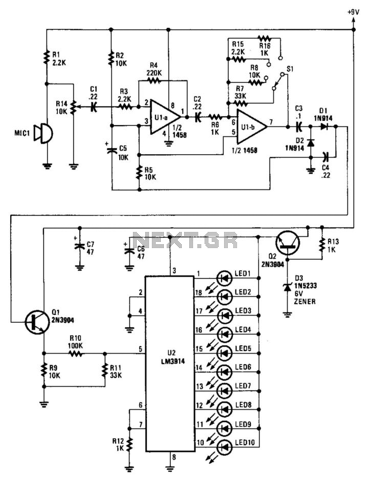
An electret microphone feeds an audio amplifier/rectifier combination. The amplifier has switchable gain. The rectifier output drives an LM3914 bar-graph generator. R14 provides fine gain control.
The circuit begins with an electret microphone, which serves as the primary audio input...
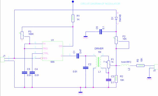
The beacon controller is designed to telemeter data from the VUSAT in Morse code, allowing ham radio operators to decode the information without requiring expensive or complex equipment. The design adheres to the KISS (Keep It Simple, Stupid) principle,...
Measuring inductance is important for creating hand-made inductors, particularly when engaging in do-it-yourself (DIY) coil winding. An inductance meter adapter can facilitate this process.
An inductance meter adapter is a vital tool for accurately measuring the inductance of coils and...
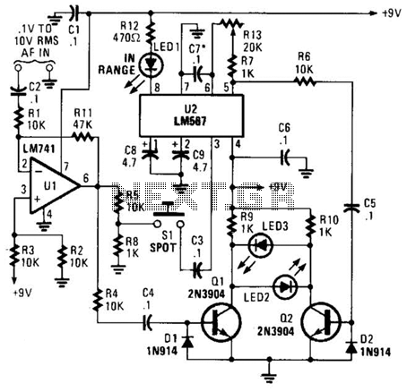
This meter is unique as it does not utilize a D'Arsonval movement or digital display for frequency readings. Instead, the measured frequency is indicated on a hand-calibrated dial. Any audio signal applied to the circuit is amplified by U1,...
We use cookies to enhance your experience, analyze traffic, and serve personalized ads.
By clicking "Accept", you agree to our use of cookies.
Learn more