
Sound-Level Meter

The circuit begins with an electret microphone, which serves as the primary audio input source. Electret microphones are widely used due to their compact size and ability to convert sound waves into electrical signals efficiently. The output from the microphone is routed to an audio amplifier that is designed to enhance the weak audio signal generated by the microphone.
This audio amplifier features switchable gain settings, allowing the user to adjust the amplification level based on the input signal strength or the desired output level. The gain can be controlled through a series of resistors or a potentiometer, enabling flexibility in various applications. The amplified audio signal is then directed to a rectifier circuit, which converts the AC audio signal into a DC voltage. This conversion is essential for driving subsequent components that require a stable DC input.
The rectifier output is connected to an LM3914 bar-graph generator. The LM3914 is a versatile integrated circuit that drives a series of LEDs or a bar graph display, visually representing the amplitude of the input signal. This makes it an excellent choice for audio level indication. The output from the rectifier feeds the LM3914, allowing it to light up the appropriate number of LEDs based on the rectified voltage level.
Additionally, resistor R14 plays a crucial role in providing fine gain control within the amplifier circuit. By adjusting R14, the user can achieve precise control over the amplification, ensuring optimal performance and signal clarity in various environments. This configuration is particularly useful in audio applications where dynamic range and signal integrity are paramount. Overall, this circuit design effectively integrates an electret microphone with an amplifier, rectifier, and visual output display, creating a comprehensive audio processing solution. An electret microphone feeds an audio amplifier/rectifier combination. The amplifier has switchable gain. The rectifier o utput drives an LM3914 bar-graph generator. R14 provides fine gain control.
Related Circuits
A capacitance meter is an essential instrument for electronics hobbyists and professional electronic technicians. A capacitance meter is a specialized device used to measure the capacitance of capacitors in electronic circuits. It is a valuable tool for diagnosing and troubleshooting...
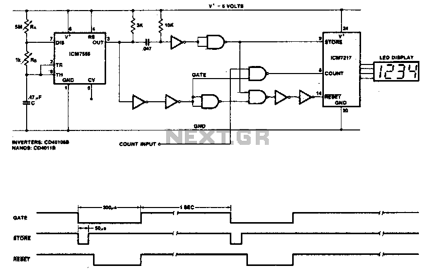
This circuit utilizes the low-power ICM7555 (CMOS 555) to generate the gating, STORE, and RESET signals. The timer is configured as an astable multivibrator to provide the gating signal. Calibration of the system is achieved using a 5 MΩ...
This project measures the clock pulses supplied to the Timer input of the AVR microcontroller. The Bascom code counts the clock pulses over a duration of 1 second and displays the result. The circuit for this project primarily consists of...
The circuit diagram illustrates a straightforward circuit design featuring 10 LEDs. It employs a series of half-wave rectification using the precision IC2 TL071, along with a single LM3915 IC that regulates the LEDs, functioning as a VU meter indicator....
This project was designed and constructed as enhancement to the 0-30V Stabilized Power Supply Project with the DIY electronics hobbyist in mind. The circuit uses a single PIC Microchip to perform the Voltage, Current and Temperature conversions and display...
Most PN-junction diodes can be utilized as photodiodes. Although they are not specifically optimized for this purpose, they are functional. When reverse biased, a diode generates a small photovoltaic output that increases with light intensity. Light Emitting Diodes (LEDs)...