
Capacitance Meter Circuit Using Transistors

The capacitance meter circuit operates by measuring the capacitance of a capacitor through a time-based method. The core of the circuit consists of a transistor-based oscillator that generates a square wave signal. This square wave is used to charge and discharge the capacitor under test.
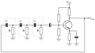
The circuit typically includes a few key components: a transistor (often an NPN type), resistors, a variable resistor (potentiometer), and a capacitor for timing purposes. The capacitor under test is connected in parallel with a timing capacitor, and the charging time of this combination is measured. The time taken for the voltage across the timing capacitor to reach a certain threshold level is directly proportional to the capacitance of the capacitor being tested.
In operation, the transistor is configured in a common-emitter configuration, which allows it to amplify the oscillation signal. The output frequency of the oscillator is influenced by the capacitance value of the capacitor being tested, which can be calculated using the formula derived from the RC time constant.
An additional feature of the circuit may include a digital display or analog meter to provide a visual representation of the capacitance value. Calibration of the circuit is essential to ensure accurate readings, which can be achieved by using known capacitance values to adjust the circuit parameters.
Overall, this transistor-based capacitance meter offers a reliable and straightforward method for measuring capacitance, making it a valuable tool for electronics enthusiasts and professionals alike.This capacitance meter circuit is similar with previous meter circuit, but it uses transistors rather than logic gates. Here is the schematic diagram: You. 🔗 External reference
Related Circuits

When the supply voltage drops below a minimum threshold, it is often advisable to disconnect the supply from the system to prevent poor performance or erratic operation. The circuit presented achieves this with minimal cost, board space, and complexity....
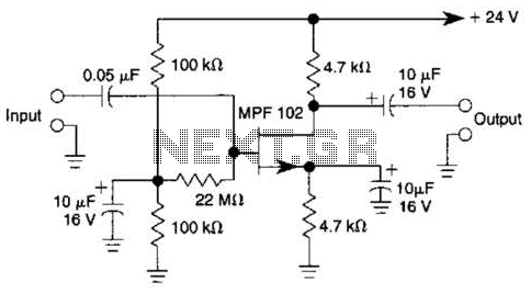
In this amplifier circuit, the gate of the MPF 102 is biased with an external voltage. This circuit achieves tighter control of the operating point and biasing conditions. The amplifier circuit utilizing the MPF 102 field-effect transistor (FET) is designed...
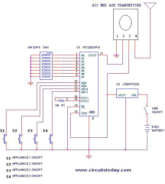
This project outlines a simple remote control system utilizing RF communication without the use of a microcontroller. The remote is designed for various home appliances such as televisions, fans, and lights, providing significant convenience by allowing operation from a...
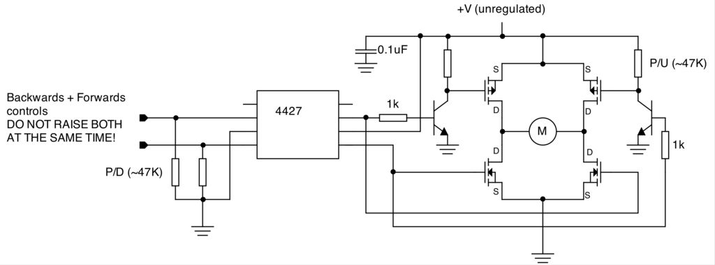
To create a versatile and generic microcontroller board, the information provided thus far is sufficient. It covers the essential components needed to achieve this. The design of a microcontroller board requires careful consideration of various factors to ensure versatility and...
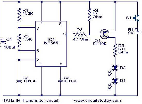
This circuit was designed in response to a request for a 1 kHz infrared (IR) transmitter circuit suitable for remote control applications. It is intended to serve as a low-power IR transmitter with an operating frequency of 1 kHz,...
For successful circuit-building exercises, follow these steps: Measure and record all component values before constructing the circuit, selecting resistor values that are sufficiently high to minimize the risk of damaging any active components. In case of significant errors (greater...