
Capacitor internal resistor meter

Building this ESR meter is simple and straightforward. I assembled the circuit on a scrap piece of project board, and used a small plastic box to install the board and the meter. The only part that could pose problems to inexperienced builders is the transformer. I made mine using an Amidon ferrite core, type EA-77-188, which is a tiny double-E core having a cross section of 22mm2, and external dimensions of about 19x16x5mm total. I used the nylon bobbin that Amidon delivers with it, wound a primary winding consisting of 400 turns of AWG #36 wire, and as secondary I wound 20 turns of AWG #26 wire. If you have a larger or smaller core, you can adjust the turn numbers in inverse proportion to the cross section area. The wire size isn't critical - the gauges I used are about 3 or 4 numbers thicker than necessary, while at the same time this bobbin has room for wire at least two numbers thicker than the ones I used. Thus, you can choose from about 6 different wire gauges for each winding, with negligible impact on the performance.
Considering that the transformer is so uncritical (because it runs at very low power), feel free to use any small ferrite core you have on hand, as long as it has no air gap. Dead PC power supplies and old monitors or TVs are great sources for such cores. Do not use an iron core, because it would probably have far too much loss at 50kHz.
The test leads are soldered into the circuit, and fixed in place using hot melt glue. Soldering them is much preferable over using any sort of connectors, because this meter easily detects resistance as low as 0.1 Ohm, and a connector can easily vary its resistance more than that! By the way, this set of test leads was bought as standard tester replacement leads, for very little money.
The meter is a reasonably good one rated at 50µA full scale, which I had on hand. If you find a cheap VU meter that works well, you can use it, of course. If you prefer to use a 100µA meter, change R11 to 50k. I used a trimpot for R11, but you might want to use a panel-mount potentiometer instead, which would allow fine adjusting the full-scale point if your meter happens to be unstable. If you use a cheap meter I would recommend this.
Using the galvanometer's original scale, adjust its set screw for accurate zero position. With the circuit powered up, short the test leads together, and adjust R11 precisely for a full-scale reading. Now, take off the meter front cover, get a pencil and a few resistors in the range of 1 to 22 Ohm or so. Using the resistors as test objects, mark the corresponding deflections on the meter scale. It's your choice if you keep this crude hand-drawn scale indefinitely, or if you use it as a template to draw a definitive scale on the computer, print it and install it in the meter. I did the latter, and you can see the results on the top of this page.
The described ESR meter operates by applying a 50kHz square wave signal to the capacitor under test, with a peak voltage of 200mV, and utilizes a 10 Ohm resistor in series for measurement. The meter's design allows for accurate readings of equivalent series resistance (ESR) without the interference typically associated with DC measurements. The operational amplifier serves dual purposes as both a square wave oscillator and a signal amplifier, ensuring that the output is suitable for the galvanometer display. The incorporation of a ferrite core transformer is critical for stepping down the voltage while maintaining low output impedance, thus enhancing measurement accuracy.
The circuit's low power consumption enables operation from various power sources, including a 9V battery or a 13.8V bus, providing flexibility for different user environments. The calibration process is straightforward, allowing for adjustments to accommodate different meter sensitivities, ensuring precise readings across a range of capacitor values. The design's simplicity and effectiveness make it an invaluable tool for electronic troubleshooting and maintenance, particularly in scenarios where capacitors are tested in-circuit, minimizing the need for component removal. The use of soldered connections instead of connectors further enhances measurement accuracy by eliminating additional resistance that could skew results. Overall, this ESR meter is a practical solution for both amateur and professional electronics technicians.The design presented here works by applying a 50kHz, 200mV square wave to the capacitor under test, in series with a 10 Ohm resistor. The AC voltage appearing across that resistor is measured and displayed on a meter. So the whole thing is nothing else than a simple ohmmeter that uses ultrasonic AC for measurement instead of the usual DC used by every common ohmmeter.
Since the Ac voltage used is so low, it does not make semiconductor junctions enter conduction, which further helps to make this meter suitable for checking capacitors mounted in a circuit. An additional beauty of an ESR meter is that in almost all cases it can check capacitors while they are in the circuit! This is so because a good capacitor would measure almost like a short circuit, and so any other parts connected in parallel will have minimal influence on the measurement.
These are the features that make an ESR meter an irreplaceable tool for troubleshooting electronic equipment. One section of a dual low power operational amplifier is used as a square wave oscillator. A small ferrite core transformer is used to step down the voltage and provide the necessary low impedance output.
A 10 Ohm resistor loads the output to absorb inductive spikes from the transformer, which could cause a false reading for low value capacitors. The other section of the op amp amplifies the signal that gets through the capacitor being tested, and its output is rectified and applied to a 50µA galvanometer through a calibration potentiometer.
A small 5 Volt regulator maintains the supply constant while the instrument is being powered from anything between about 7 and 15 Volt. I power the meter from the 13.8V bus which I have in my workshop, but if you prefer, you can use a 9V battery instead, connected through a switch.
The power consumption of this circuit is so low that a 9V battery should last at least 100 hours. Building this ESR meter is simple and straightforward. I assembled the circuit on a scrap piece of project board, and used a small plastic box to install the board and the meter. The only part that could pose problems to inexperienced builders is the transformer. I made mine using an Amidon ferrite core, type EA-77-188, which is a tiny double-E core having a cross section of 22mm2, and external dimensions of about 19x16x5mm total.
I used the nylon bobbin that Amidon delivers with it, wound a primary winding consisting of 400 turns of AWG #36 wire, and as secondary I wound 20 turns of AWG #26 wire. If you have a larger or smaller core, you can adjust the turn numbers in inverse proportion to the cross section area.
The wire size isn't critical - the gauges I used are about 3 or 4 numbers thicker than necessary, while at the same time this bobbin has room for wire at least two numbers thicker than the ones I used. Thus, you can choose from about 6 different wire gauges for each winding, with negligible impact on the performance.
Considering that the transformer is so uncritical (because it runs at very low power), feel free to use any small ferrite core you have on hand, as long as it has no air gap. Dead PC power supplies and old monitors or TVs are great sources for such cores. Do not use an iron core, because it would probably have far too much loss at 50kHz. The test leads are soldered into the circuit, and fixed in place using hot melt glue. Soldering them is much preferable over using any sort of connectors, because this meter easily detects resistance as low as 0.1 Ohm, and a connector can easily vary its resistance more than that!
By the way, this set of test leads was bought as standard tester replacement leads, for very little money. The meter is a reasonably good one rated at 50µA full scale, which I had on hand. If you find a cheap VU meter that works well, you can use it, of course. If you prefer to use a 100µA meter, change R11 to 50k. I used a trimpot for R11, but you might want to use a panel-mount potentiometer instead, which would allow fine adjusting the full-scale point if your meter happens to be unstable.
If you use a cheap meter I would recommend this. Using the galvanometer's original scale, adjust its set screw for accurate zero position. With the circuit powered up, short the test leads together, and adjust R11 precisely for a full-scale reading. Now, take off the meter front cover, get a pencil and a few resistors in the range of 1 to 22 Ohm or so.
Using the resistors as test objects, mark the corresponding deflections on the meter scale. It's your choice if you keep this crude hand-drawn scale indefinitely, or if you use it as a template to draw a definitive scale on the computer, print it and install it in the meter. I did the latter, and you can see the results on the top of this page. 🔗 External reference
Related Circuits
The tachometer, also known as a revolution counter, is an instrument that measures the speed of rotating machinery, typically expressed in revolutions per minute (RPM). This project involves creating a custom sensor using a light-emitting diode (LED) as a...
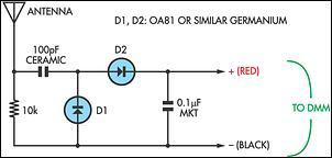
Many passive field strength meters have appeared in the past, typically using a 50mA analog meter movement if reasonable sensitivity was to be obtained. Passive field strength meters are essential tools used for measuring electromagnetic fields. The design of...
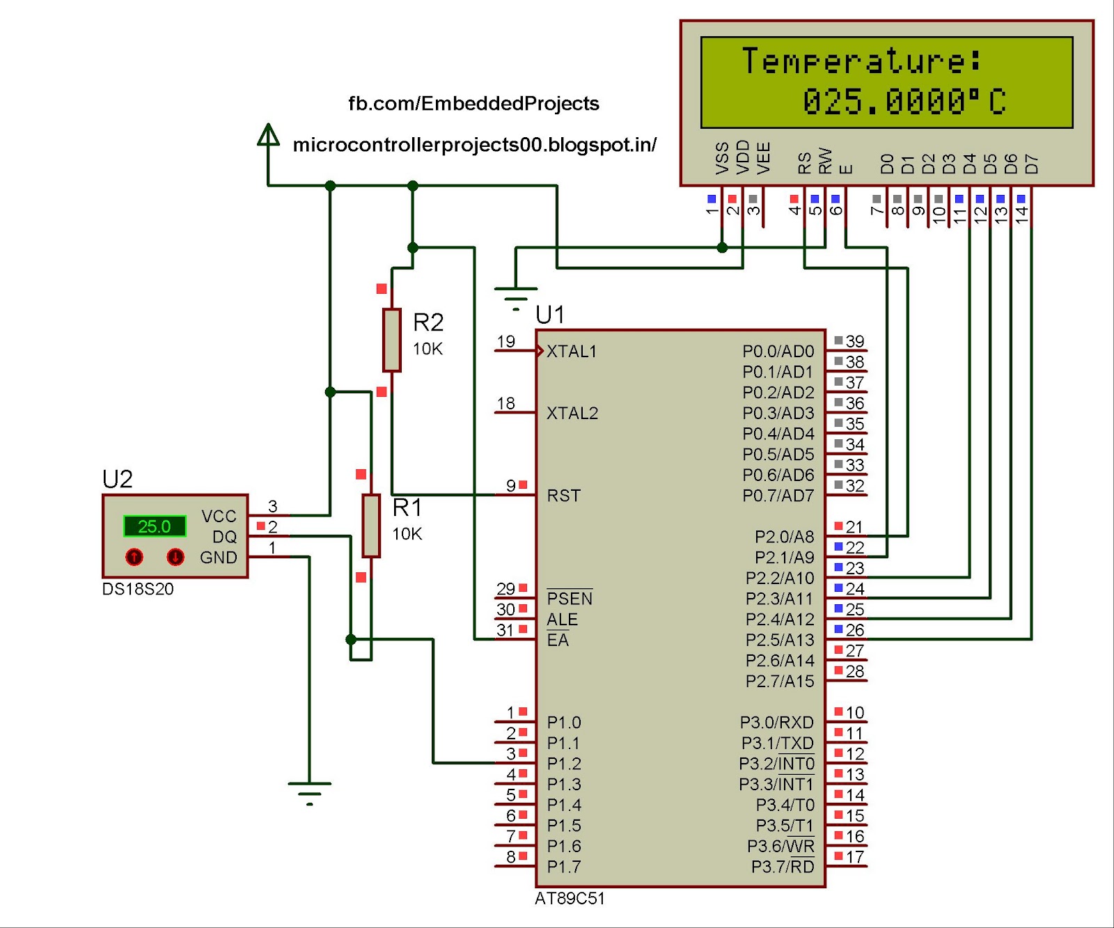
The hardware configuration for utilizing multiple 1-Wire temperature sensors, such as the DS1820, is straightforward. Communication between the microcontroller and the temperature sensors occurs over a single-wire bus, which can also supply power to the devices. An extensive number...
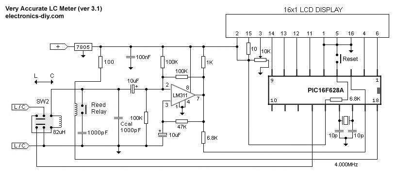
This is one of the most accurate and simplest LC inductance / capacitance Meters that one can find, yet one that you can easily build yourself. This LC Meter allows to measure incredibly small inductances starting from 10nH to...
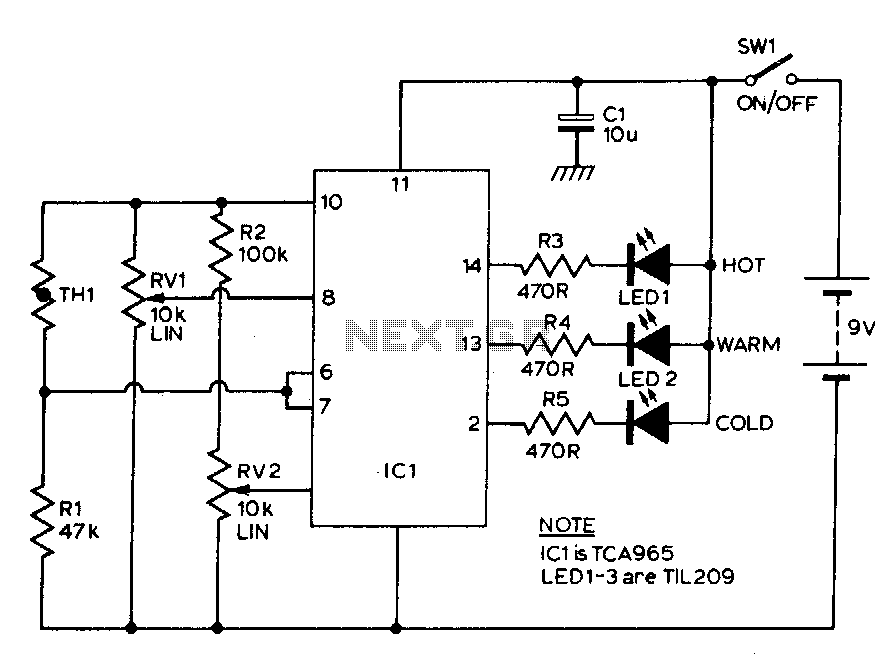
The TCA965 window discriminator IC enables the use of potentiometers RV1 and RV2 to configure the window height and window width, respectively. Resistor R1 and thermistor TH1 form a potential divider connected across the supply lines. Resistor R1 is...
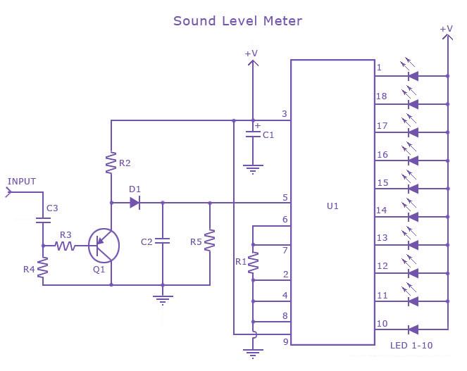
This is a single-chip sound level meter that can be used to display the sound level of an amplifier or simply the sound level from a microphone. The core component of the circuit is the IC LM3915 Audio Level...