
Cellular Phone calling Detector

This circuit operates on the principle of electromagnetic induction to detect the RF signal emitted by a cellular phone during an incoming call. The sensor coil, L1, is critical to the circuit's functionality. By winding 130 to 150 turns of 0.2 mm enameled wire around a 5 cm diameter former, the coil is able to capture the low-frequency electromagnetic fields generated by the phone. The placement of the circuit near the phone is essential, as the sensitivity of the detection is directly related to the proximity of the sensor to the phone's receiver.
Once the signal is detected by L1, it is fed into transistor Q1, which serves as an amplifier. This transistor is configured in a common-emitter arrangement, allowing it to amplify the weak signal from the coil. The amplified output from Q1 is then connected to the monostable input pin of the integrated circuit IC1, which is typically a timer IC such as the 555 timer. The monostable configuration allows the IC to produce a single output pulse when triggered by the incoming signal, which is essential for driving the LED.
The output from IC1 is then processed by a voltage doubling circuit composed of capacitor C2 and diode D2. This stage is crucial for ensuring that the output voltage is sufficient to drive the ultra-bright LED. The LED is chosen for its high efficiency and brightness, ensuring that the visual indication of an incoming call is prominent even in bright ambient light conditions.
The design of this circuit emphasizes low power consumption, with a standby current draw of less than 200µA. This allows for continuous operation without the need for a power switch, making it convenient for users. The overall effectiveness of the circuit can be influenced by the choice of components, particularly the sensor coil, which must be tailored to the specific application and environment in which the circuit operates.This circuit was designed to detect when a call is incoming in a cellular phone (even when the calling tone of the device is switched-off) by means of a flashing LED. The device must be placed a few centimeters from the cellular phone, so its sensor coil L1 can detect the field emitted by the phone receiver during an incoming call.
The signal detected by the sensor coil is amplified by transistor Q1 and drives the monostable input pin of IC1. The IC`s output voltage is doubled by C2 & D2 in order to drive the high-efficiency ultra-bright LED at a suitable peak-voltage.
# Stand-by current drawing is less than 200µA, therefore a power on/off switch is unnecessary. Sensitivity of this circuit depends on the sensor coil type. L1 can be made by winding 130 to 150 turns of 0.2 mm. enameled wire on a 5 cm. diameter former (e.g. a can). 🔗 External reference
Related Circuits
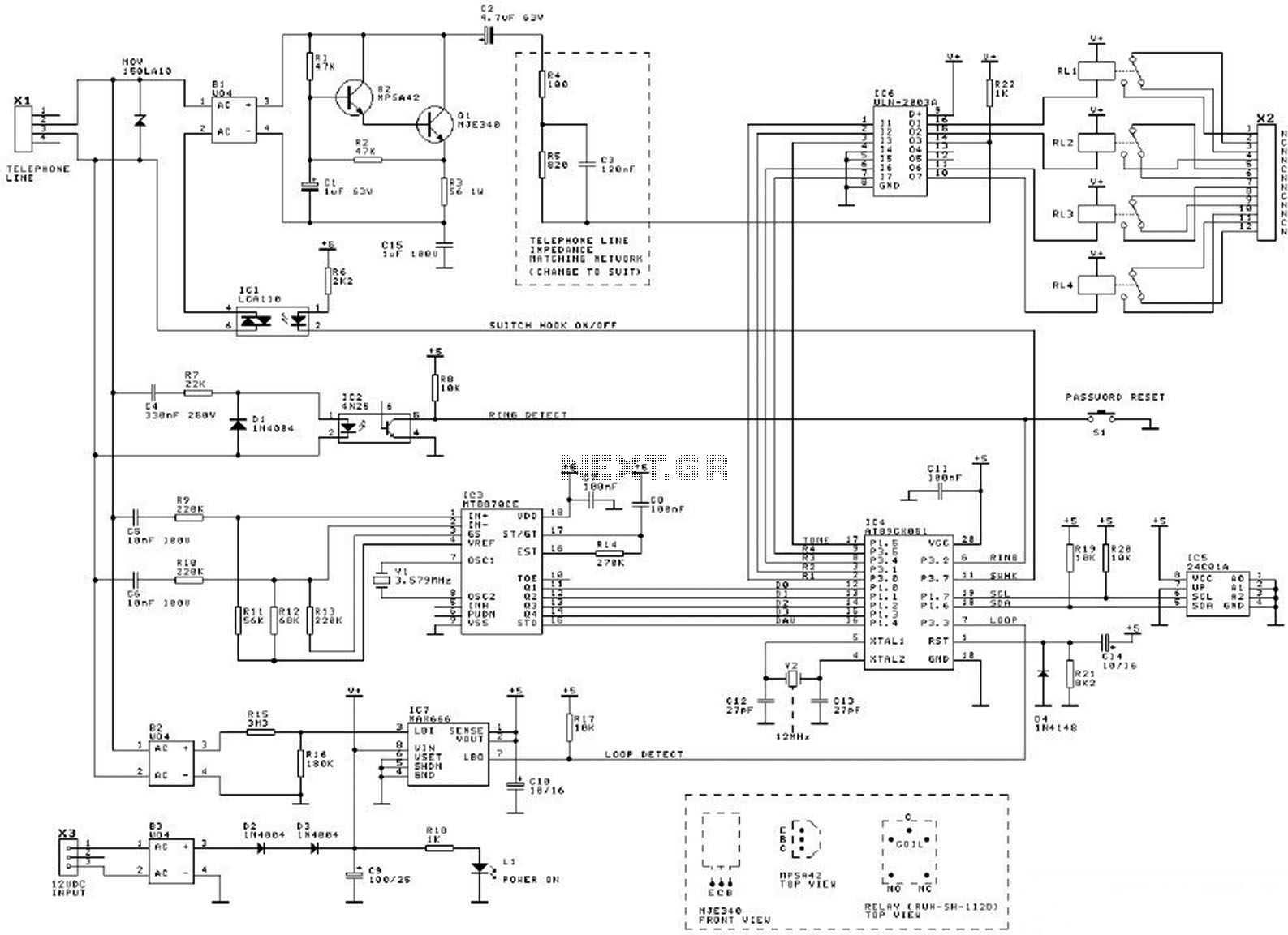
This diagram illustrates the schematic of a telephone switcher that utilizes relays. The device interfaces with the telephone line and allows for remote control of up to four relay outputs through a DTMF (dual-tone multi-frequency) telephone. Several user-configurable settings...
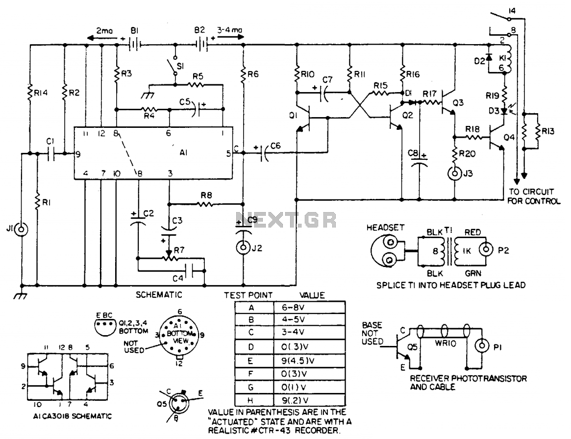
The laser light detector employs a sensitive phototransistor (Q5) positioned at the focal point of a lens (LE2). The output from Q5 is directed to a sensitive amplifier composed of an array (A1), which is biased through a voltage...
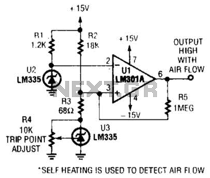
Two precision temperature sensors are utilized to measure a slight temperature difference. When airflow is present, the self-heating of the LM335 is minimized, resulting in an unequal output from the two temperature sensors. This disparity is further amplified by...
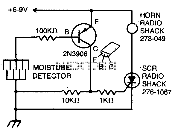
The detector consists of fine wires spaced approximately one to two inches apart. When the area between a pair of wires becomes moist, an alarm will sound. To deactivate the alarm, the DC power must be disconnected. The described moisture...
This circuit is designed for liquid level or proximity detection. It operates by measuring the distance to a target through the reflection of an infrared beam. The device can detect the level of liquid in a tank without any...
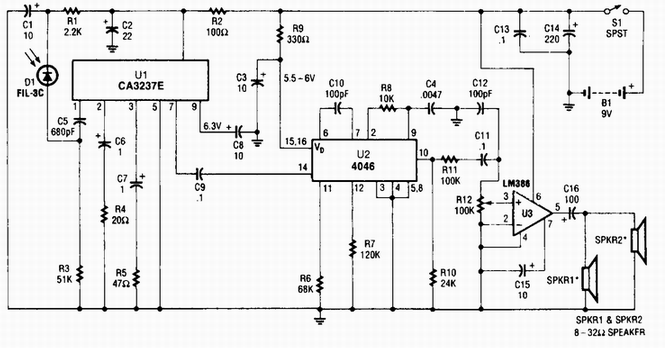
A photodiode D1 feeds a high-gain infrared (IR) remote control preamplifier IC, specifically a CA3237E. U2 is a phase-locked loop (PLL) frequency modulation (FM) detector tuned to approximately 100 kHz. The output from the detector is amplified by U3,...