
Centrifugal fish autofeeder

The automatic fish feeder circuit consists of several key components that work together to achieve its intended functionality. The heart of the circuit is the 555 timer IC, which is configured in astable mode to generate a continuous pulse output. This output is fed into two cascaded CMOS 4017 decade counters, which count the pulses from the timer and provide a means to extend the timing intervals significantly.
The first CMOS 4017 counter receives the pulse output from the 555 timer. Each pulse increments the count, and when the count reaches ten, it triggers the second counter. This cascading configuration allows for a multiplication of the time intervals, enabling the user to set extended feeding cycles. The output from the second counter is routed to a relay, which controls the feeding mechanism.
The relay serves as a switch that activates the motor responsible for dispensing the fish pellets. When the relay is energized, it closes the circuit, allowing current to flow to the motor. The motor operates for a duration determined by the charge time of the capacitor. The capacitor charges through the relay, and its capacitance value directly affects the length of time the relay remains activated. A larger capacitor will hold a charge longer, thus keeping the relay engaged for an extended period.
To ensure the capacitor is ready for the next cycle, a resistor is connected in parallel, allowing the capacitor to discharge after each feeding cycle. This setup ensures that the circuit resets appropriately for the subsequent feeding interval.
The circuit's design allows for easy adjustments. The feeding intervals can be modified by changing the resistance value of the variable resistor (R-Var) connected to the timer. Similarly, the amount of food dispensed can be adjusted by selecting different capacitor values (C-Var), providing flexibility to accommodate various fish species and feeding habits.
Overall, this automatic fish feeder circuit not only simplifies the process of fish feeding but also serves as an engaging project for electronics enthusiasts. Its straightforward design and adjustable parameters make it a practical solution for ensuring that fish receive adequate nourishment even in the absence of their owner.This easy as well as cheap but effective device is mainly intended for your ease to leave your fish autofed. You need no longer worry your fish would starve as this autofeeder would replace your job. This autofeeder device will expell pellets byquantityas well astime intervalsas you like. Besides, making this circuit seems to be a bit entertaining as you are insisted to make it yourself and so It would develop your creativity. Don t worry, it works! The main role of this section functions as a timer (few hour intervals) with progress indicator and the mutual action of the relay and capasitor functioning as expelled quantity of pellets. The circuit is using regular timer (IC 555) sending pulse to 2 cascaded counters of CMOS 4017. The output pin from the last counter is then fed to the capacitor and-relay in series. (Remember: a relay owns its own resistance) which consequently trigger the relay for some time to turn on mechanics section.
After the capacitor is about to be fully loaded, the relay shuts off. From here we could figure out that the bigger the capacity the longer the relay connects which then causes the motor works to expel pellets centrifugally. The resistor functions to unload the capacitor so that the capacitor is then ready to be loaded for the next cycle.
For short, if we set the timer T = 3 minutes, the both counters will multiply the time to be 10 x 10 = 100 times. So the total time intervals would be T = 3 minutes x 10 x 10 = 300 minutes = 5 hours. To change the time intervals simply is by changes/turning R-Var and for the pellet quantity is by changing C-Var size.
🔗 External reference
Related Circuits
The fishing circuit, as illustrated in figure 11-6, comprises a timing circuit and an audio circuit. The components 555, RP1, and C1 form the single-shot circuit, with the defined time calculated as td = 1.1RP1C1. The maximum defined time...
These items were sold nationally several years ago. The fish would sing, open its mouth, turn its head, and flap its tail. After removing the back panel, all of the existing electronics were removed leaving only the 3 servo...
The electronic fishing shrimp machine circuit consists of an astable oscillator, an inverter circuit, and a high-voltage output circuit, as depicted in Figure 20. The astable oscillator circuit includes a time-base integrated circuit (IC), resistors R3 and R4, a...
When the tank is cleaned the fish are removed and placed in a small amount of the tank water. The problem is that fish don’t like rapid temperature fluctuations. A simple in-tank or stick-on thermometer would have sufficed, but...
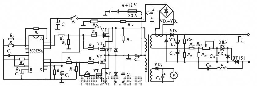
The circuit utilizes the SC3525A, a PWM silicon chip from US General Semiconductor. It features an error amplifier with an inverting input at pin 1. Pin 2 serves as the non-inverting input for the error amplifier. Pins 5 and...
The block diagram illustrating the device and operation of the sonic depth finder is depicted in Figure 1. The clock generator G1 facilitates the interaction of the device's components, enabling automatic functionality. It generates short rectangular pulses of positive...