
Cheap frequency meter by CA3130

The input signal is fed into IC1 through capacitor C1, which blocks any potential DC current. Resistors R1, D1, and D2 limit the input signal size to prevent damage to IC1 by ensuring the voltage drop across the diodes remains within safe limits. Resistors R5 and R6 create positive feedback, establishing hysteresis around the zero voltage level of the input signal, which helps mitigate interference from noise. To facilitate operation with a single power supply, resistors R2 and R3 bias the input pin of IC1 to approximately half the supply voltage. The output from pin 6 of IC1 produces a square wave with a frequency equal to the input signal. This square wave is then differentiated into narrow pulses using capacitor C3 and resistors R7 and R8, with their values selected to ensure the pulse width is less than that generated by IC2, thus ensuring reliable operation. These narrow pulses serve as the triggering signal for the monostable multivibrator, enabling accurate frequency measurement.This cheap frequency meter circuit that we show to you. Suitable for general use in small laboratories. Because cheap, easy to build. And Qualified enough. For applications most of the electronics amateur. It can be shown that the frequency read directly from the meter. Can measure the frequency of 100 Hz (full scale) to 100KHz (full scale). By the characteristics of the waves do not affect the accuracy of the circuit. Even low levels, can be measured to a hundred millivolts. (100mV) The working principle of the cheap frequency meter is simple. Internal its there is a generates narrow pulses circuit up. By same frequency as the signal to be measured. These pulses will go to make a meter needle swing more or less. By an average of caused by current pulses. Which the average value will be ratio with amount of pulses that occur in a time period. The signal that is measured has a low frequency and amount of pulse will be few. The current average flow meter is less. But if the signal that is measure has high frequency, number of pulse too much will has the high average current makes the meter needle swing up. So, We can set the width of each pulse constant, then The swing of the meter needle is in proportion to the frequency of signal that is measured there.
We so adjust the scale of meter to read value as frequency It directly with a linear scale. (each channel of the scale are spaced evenly. ) -In figure 1 is the complete circuit of the cheap frequency meter. This circuit uses two ICs are CA3130 and LM555. The first is a OP-amp Ic is work faster and has the input impedance is very high. This IC is connected as the schmitt trigger circuit to extend the input signal to act up and force you to convert the input signal to a square wave with a fixed height. For the second IC as a timer IC NE555 which is connected as a monostable multivibrator circuit. It will be provides pulse width at the output every time, when has a input complete 1 wave. This pulse will be entered to drive a Moving Coil Type Meter The meter needle indicates an average voltage value of pulse.
Which the needle is pointing more or less in proportion to the frequency of input signal. -When you know the principle roughly, to view the detail of the works. The input signal will be entered to IC1 by through the capacitor C1 to block a DC current that might be coming campsites. They R1, D1 and D2 will act limit size of the input signal is not too higher than voltage drop across diode.
While is directed bias to not high until damage to the IC1, R6 and R5 act feed back a positive mode, To create a hysteresis in the area around the level zero voltage of the input signal. Having the hysteresis allows the circuit to be less interference from the noise signal. -Sine this circuit uses a single power supply source to convenience, so must connect the R2 and R3 to bias to the input pin of IC1 is about half of the power supply.
The output from pin 6 of IC1 will be the square wave. Which has frequency equal to the input signal. The square wave signal will be differentiated onto as narrow pulse like a needle shape with C3, R7 and R8. The value of these is assigned to a needle pulse width less than pulse that IC2 will be created. To ensure that IC2 can function correctly, and high reliability. -This needle Pulse act as signal that enter into trigger to the monostable multivibrator circuit works.
The width of pu 🔗 External reference
Related Circuits
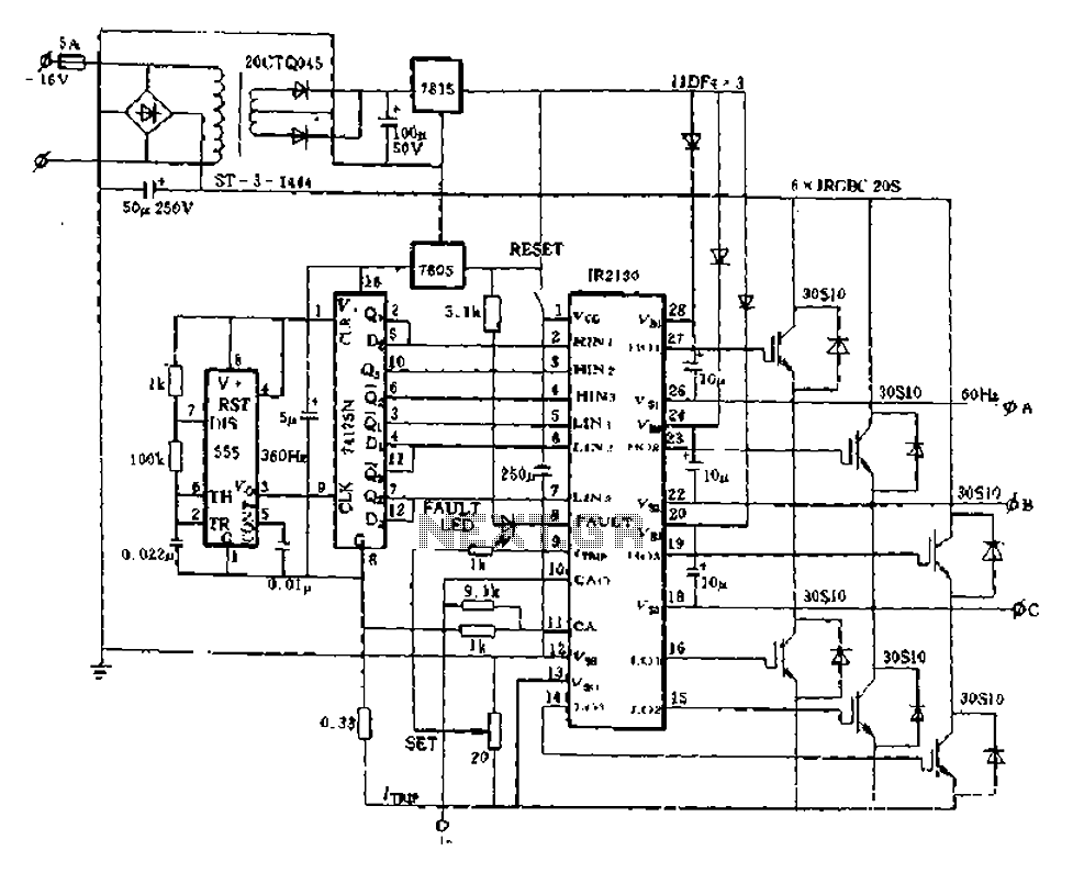
The application of the aforementioned advantages allows the IR2130 to be effectively utilized for DC cut crossing speed, DC servo systems, three-phase power inverters, and switching power supplies. Additionally, it is applicable in inverter power supplies, uninterruptible power supplies...
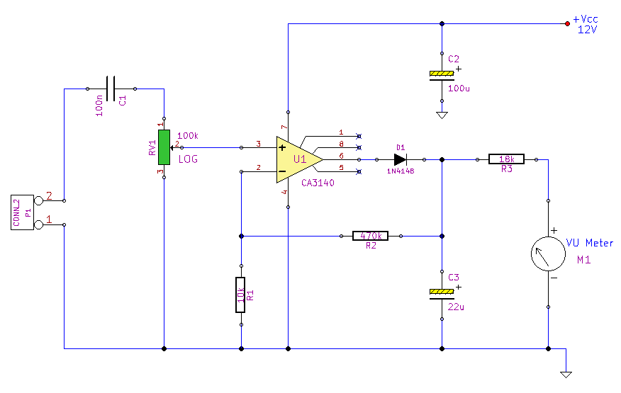
This simple circuit, designed with a minimal component count, indicates peak audio response on an analog meter, similar to a tape recorder's meter. It employs an operational amplifier configured as a non-inverting amplifier, with the addition of a diode...
Crystals typically function at fundamental frequencies of up to approximately 15 MHz. When higher frequencies are necessary, a frequency multiplier is employed following the crystal. Frequency multipliers are essential components in electronic circuits, especially when higher frequency signals are needed...
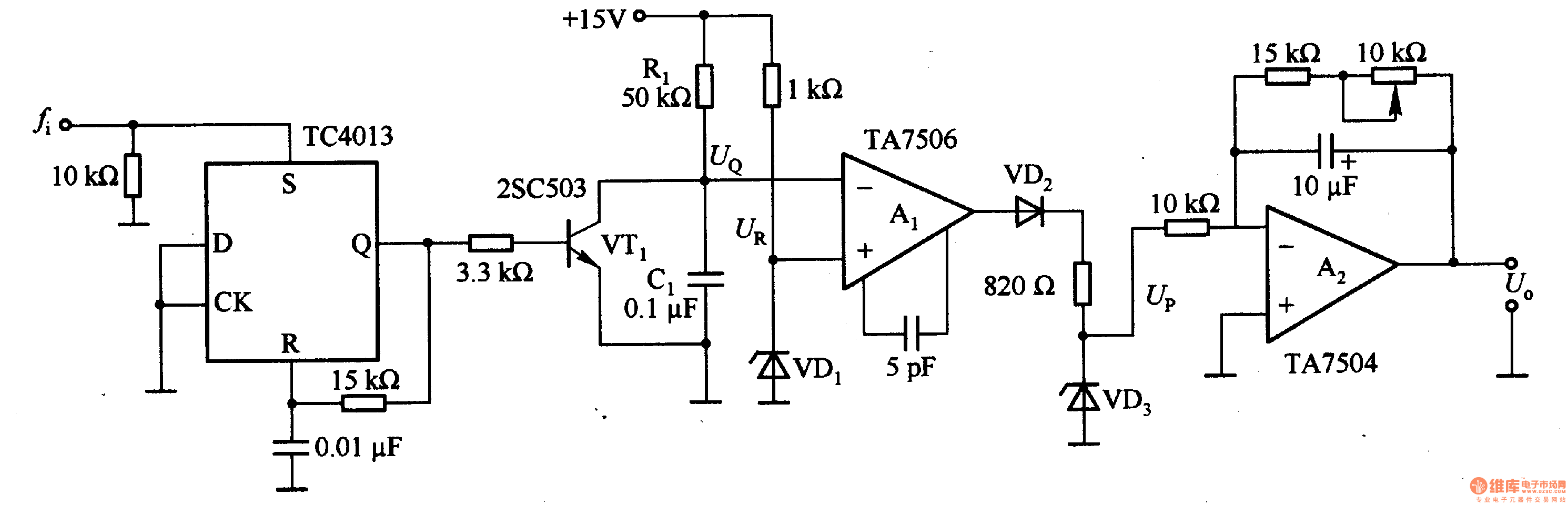
This circuit can convert an input frequency ranging from 0 to 100 Hz into an output voltage of 0 to 10 V. It utilizes the TC4013 monostable multivibrator to shape and amplify the input pulse, which has a width...
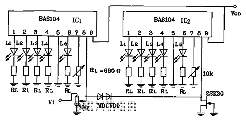
BA6104 is a five-digit LED level meter that functions as an LED display driver integrated circuit (IC). The configuration of the circuit is illustrated in the accompanying figure. The circuit utilizes a 10 by two-dot LED level display. The...

A remote sensor transmits data through the mains supply, with a temperature range of 00.0 to 99.9 °C. This circuit is designed for precise centigrade temperature measurement. The circuit employs a remote temperature sensor that communicates its readings over the...