
CMOS Crystal Frequency Multiplier

Frequency multipliers are essential components in electronic circuits, especially when higher frequency signals are needed beyond the limitations of standard crystal oscillators. A frequency multiplier works by taking an input signal at a specific frequency and generating an output signal at a frequency that is a multiple of the input frequency.
In the context of crystal oscillators operating at fundamental frequencies up to 15 MHz, the frequency multiplier can significantly enhance the performance of the circuit. For instance, if a crystal oscillator operates at 10 MHz, a frequency doubler can be used to produce a 20 MHz output. This is achieved through non-linear processes, often involving diodes or transistors configured in specific ways to achieve the desired multiplication factor.
The design of a frequency multiplier involves careful consideration of the circuit topology, the components used, and the desired output frequency. Common configurations for frequency multiplication include the use of harmonic generation techniques, where the input signal is applied to a non-linear device that generates harmonics of the input frequency. Filters are then employed to isolate the desired harmonic and suppress unwanted frequencies.
Additionally, the choice of components such as inductors, capacitors, and the non-linear devices themselves can greatly influence the efficiency and performance of the frequency multiplier. Proper impedance matching is also crucial to ensure maximum power transfer and minimize signal loss.
In summary, frequency multipliers serve as vital tools in electronic design, enabling the generation of higher frequency signals from lower frequency crystal oscillators, thereby expanding their application in various fields such as telecommunications, signal processing, and RF communication systems.Crystals usually operate at fundamental frequencies up to about 15 MHz. Whenever higher frequencies are required a frequency multiplier is placed after th.. 🔗 External reference
Related Circuits
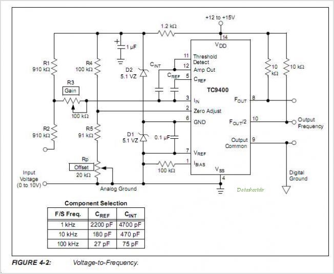
The TC9400, TC9401, and TC9402 are low-cost voltage-to-frequency (V/F) converters that utilize low-power CMOS technology. These converters accept a variable analog input signal and generate an output pulse train, with a frequency that is linearly proportional to the input...
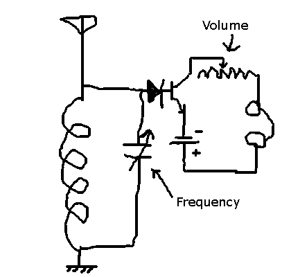
This circuit allows the selection of a station by adjusting the capacitance in an LC circuit. However, the signal remains modulated. To demodulate the signal, a second capacitor is required, but the function of this component is unclear. The...
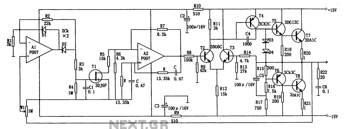
The low-frequency signal generating circuit demonstrates excellent performance characterized by stable operation, high output power, and minimal waveform distortion. It serves as an ideal source for low-frequency measurement signals. The circuit includes an operational amplifier (A) with a feedback...
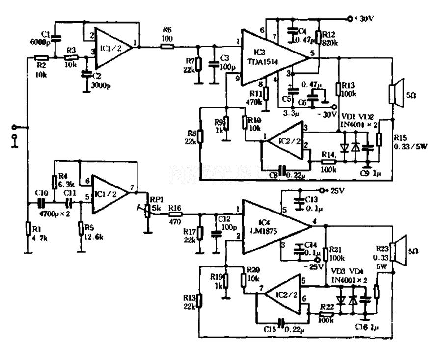
The mechanical and electrical schematic in Figure 5 illustrates a simple circuit comprising several components. The first component is an electronic crossover section utilizing the NE5532 operational amplifier, which is known as the "Emperor of the op-amp." This section...
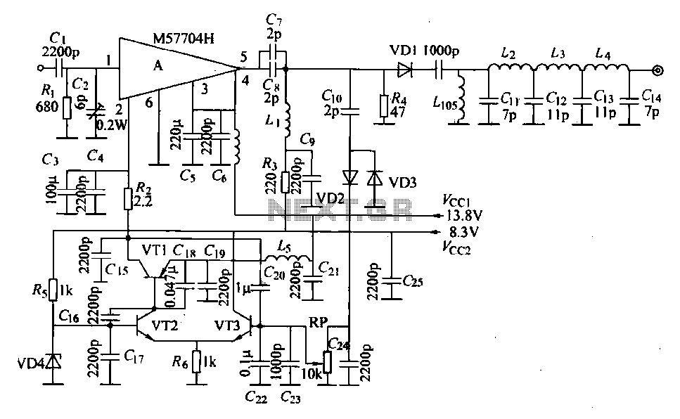
The FM radio transmitter is a high-frequency amplifier circuit that utilizes the Mitsubishi frequency set, specifically the M57704H discharge path. It operates within the frequency range of 457-458 MHz and has a transmission power of 5 watts. As illustrated...
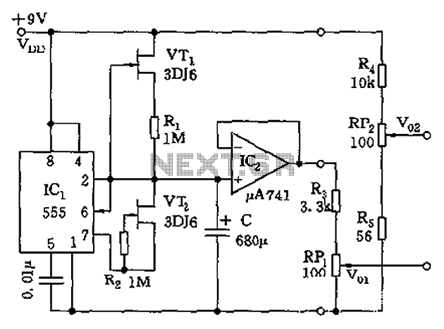
The circuit depicted in the figure is a generator that includes an oscillator, a voltage follower, a zero amplitude adjustment, and a zero shift circuit. It is utilized as a self-balancing recorder for testing signals. The output signal ranges...