
A simple remote control tester circuit diagram

This IR remote control tester circuit utilizes a straightforward design to effectively detect and indicate the presence of IR signals. The core component of this circuit is the IR sensor module, which is sensitive to the modulated IR light emitted by remote controls. When an IR signal is received, the sensor's output transitions to a low state, triggering the transistor T1. This transistor acts as a switch, allowing current to flow to the LED1 and buzzer BZ1, thus providing a visual and audible indication of the received signal.
The circuit's power supply is critical for its operation. A 9V power adapter is used to provide the necessary voltage, which is then regulated down to 5V for the circuit's components. Capacitors C1 and C2 play essential roles in ensuring stable operation; C1 filters the DC voltage to eliminate any fluctuations, while C2 prevents voltage spikes that could potentially damage the circuit.
The physical design of the tester is also noteworthy. The use of a plastic-molded sensor allows for compact integration into a metal housing, with the sensor positioned to extend outside the enclosure. This design minimizes the footprint of the device while ensuring that the sensor can effectively detect IR signals without obstruction. Grounding the metal case is important to prevent interference from external electromagnetic sources, which could lead to false readings or erratic behavior of the circuit.
Overall, this IR remote control tester circuit is a practical and efficient tool for verifying the functionality of remote control devices, providing clear visual and auditory feedback in response to IR signals.Here is a handy gadget for test- ing of infrared (IR) based re- mote control transmitters used for TVs and VCRs etc. The IR signals from a remote control transmitter are sensed by the IR sensor module in the tester and its output at pin 2 goes low.
This in turn switches on transistor T1 and causes LED1 to blink. At the same time, the buzzer beeps at the same rate as the incoming signals from the remote control transmitter. The pressing of different buttons on the remote control will result in different pulse rates which would change the rate at which the LED blinks or the buzzer beeps. When no signal is sensed by the sensor module, output pin 2 of the sensor goes high and, as a result, transistor T1 switches off and hence LED1 and buzzer BZ1 go off.
This circuit requires 5V regulated power supply which can be obtained from 9V eliminator and connected to the circuit through a jack. Capacitor C1 smoothes DC input while capacitor C2 suppresses any sudden spikes appearing in the input supply.
Here, a plastic moulded sensor has been used so that it can easily stick out from a cut in the metal box in which it is housed. It requires less space. Proper grounding of the metal case will ensure that the electromagnetic emissions which are produced by tube-lights and electronic ballasts etc (which lie within the bandwidth of receiver circuit) are effectively grounded and do not interfere with the functioning of the circuit.
The proposed layout of the box containing the circuit is shown in the figure. The 9-volt DC supply from the eliminator can be fed into the jack using a banana-type plug. Tech. Editor s note: In fact, the complete gadget can be assembled in the eliminator s housing itself and a cut can be made in its body for exposing the IR module s sensor part. Disclaimer: All the information present on this site are for personal use only. No commercial use is permitted without the prior permission from authors of this website. All content on this site is provided as is and without any guarantee on any kind, implied or otherwise.
We cannot be held responsible for any errors, omissions, or damages arising out of use of information available on this web site. The content in this site may contain COPYRIGHTED information and should not be reproduced in any way without prior permission from the authors.
🔗 External reference
Related Circuits
The 27MHz quartz crystal oscillator circuit is illustrated in figure 1. The biasing circuit consists of resistors R1, R2, and R3, while C6 serves as the bypass capacitor. The partial voltage circuit includes capacitors C1, C2, C3, and C4...
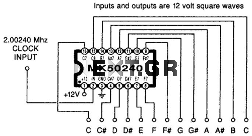
Using an MK50240, this circuit generates 12 top octave tones. The input and output lines can be separated using a binary divider IC to achieve the lower notes. Inputs and outputs are 12-volt square waves. The MK50240 is a specialized...
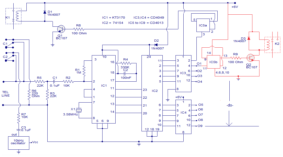
The circuit is a remotely operated DTMF telephone system capable of controlling up to nine devices using the keys 0 to 9 on a phone. The digit 0 is utilized to switch between the phone system remotely and alter...

The prototype was successfully assembled on a breadboard and subsequently built on a piece of Radio Shack protoboard for field use. The assembly process took only a couple of hours, and it functioned correctly on the first attempt. This...

A CMOS clock circuit is capable of driving a multi-digit gas discharge display. This simple circuit does not include an alarm feature but allows for a flashing colon to indicate morning and afternoon. The circuit requires seven drive circuits...
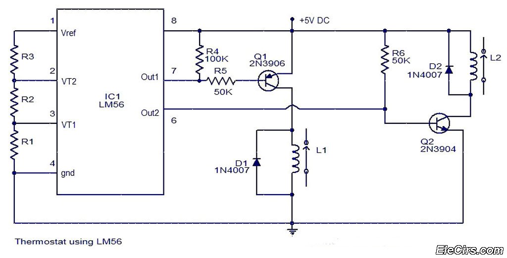
The LM56 Thermostat Project Circuit Diagram includes a schematic for the LM56 thermostat. The values of resistors R1, R2, and R3, which determine the required trip points VT1 and VT2, can be calculated using the following equations: VT1 =...