
AM sofware radio using Arduino

The described AM radio transmitter employs an Arduino microcontroller to generate amplitude-modulated signals suitable for radio broadcasting. The audio input, which can be derived from various sources such as a microphone or audio player, is first processed by the Analog-to-Digital Converter (ADC) of the Arduino. The decoupling capacitor serves to filter out any high-frequency noise from the audio signal, ensuring that only the desired audio frequencies are sent to the ADC for conversion.
Once the audio signal is digitized, the Arduino utilizes Pulse Width Modulation (PWM) to modulate the amplitude of the signal. This is accomplished through a dedicated PWM output pin, which drives a capacitor-inductor (LC) circuit. The LC circuit is crucial for tuning the transmitter to the desired frequency and for efficiently coupling the modulated signal to the antenna. The antenna itself is responsible for radiating the AM signal over the airwaves, allowing it to be received by standard AM radio receivers.
The schematic of the circuit would typically include the Arduino connections, the arrangement of the decoupling capacitor, the PWM output configuration, and the LC circuit design parameters. Additionally, the firmware would contain the necessary code to handle audio input processing, PWM signal generation, and potentially user interface elements for tuning and configuration.
The availability of both the schematic and firmware facilitates replication and further experimentation, allowing users to modify parameters and enhance the transmitter's performance according to specific needs or preferences.Markus built a software AM radio transmitter using the Arduino. The audio signal is fed to the ADC input through a decoupling capacitor. A PWM output pin directly drives a capacitor inductor circuit with an antenna. The schematic and firmware are available. 🔗 External reference
Related Circuits
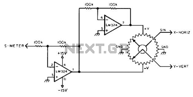
To display polar quantities, which include both the magnitude and direction of a received radio signal, a sine and cosine voltage proportional to an angle corresponding to the antenna direction is required. This setup utilizes a sine-cosine potentiometer connected...
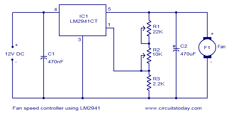
Numerous electronic circuits designed for fan speed control have been documented, and this one presents an alternative method. The circuit diagram illustrates a 12V DC fan speed controller utilizing the LM2941CT integrated circuit, which is a low dropout 1A...
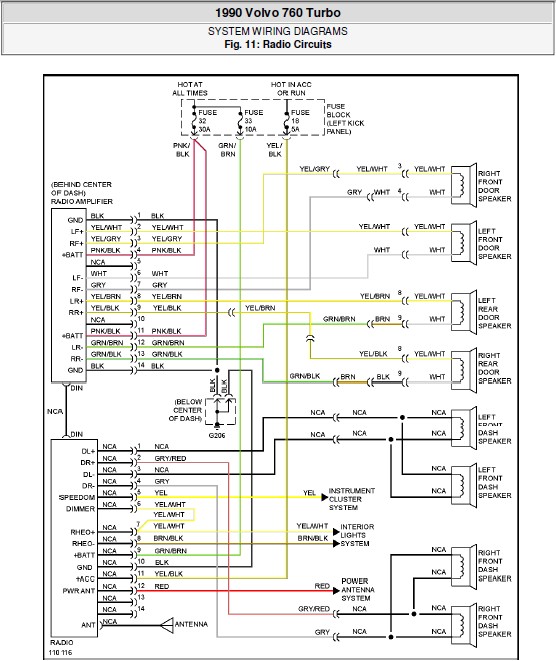
The following document contains the system wiring diagram of the radio circuit for the Volvo 760 Turbo 1990. Please note that this is a system wiring diagram, not a schematic diagram. Download the radio circuit system wiring for the...
The microphone amplifier/modulator is built around the LM324, which is a quad operational amplifier that provides sufficient quality amplification for the voice captured by the condenser microphone. The LM324 is a versatile quad op-amp that consists of four independent, high-gain,...
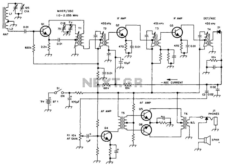
A schematic of a typical transistor AM radio is presented. This circuit utilizes npn transistors. It is a generic circuit; hence, specific values for some components are not provided. This circuit serves as a reference point for experimenters. The schematic...

This is a simple circuit of an FM booster designed to enhance the reception of programs from distant FM stations. The amplifier effectively captures signals from far-off FM stations. The configuration is set up as a common-emitter tuned RF...