
Arduino Motion Detector Circuit
The described circuit utilizes a PIR motion sensor connected to an Arduino microcontroller to create a simple motion detection system. The PIR sensor is sensitive to infrared radiation, which allows it to detect the presence of moving objects, particularly those that emit heat, such as humans or animals. The sensor's output is a digital signal indicating whether motion is detected. When the sensor detects motion, it sends a HIGH signal to the Arduino, which can then execute programmed instructions, such as activating an LED.
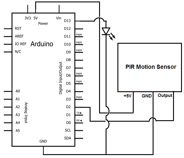
In terms of circuit design, the PIR motion sensor is powered by a regulated DC voltage supplied through pin 1, while pin 2 connects to ground, ensuring proper operation of the sensor. The output pin, pin 3, is connected to a digital input pin on the Arduino (D3 in this case), allowing the microcontroller to monitor the PIR sensor's output. The Arduino is programmed to respond to changes in the signal from the PIR sensor, turning the LED on for a specified duration when motion is detected.
The Arduino code is structured to initialize the pins, read the input from the PIR sensor, and control the LED based on the sensor's output. The use of the delay() function allows for customization of how long the LED remains lit after motion is detected, offering flexibility based on user requirements. This project serves as an excellent introduction to working with sensors and microcontrollers, illustrating fundamental concepts in electronics such as signal processing, voltage regulation, and programmable logic.
Overall, this motion detection circuit is a practical application that can be expanded or modified for various uses, such as security systems, automated lighting, or interactive installations, demonstrating the versatility of the Arduino platform and PIR sensor technology.For example, once the motion sensor picks up motion, we can program the arduino to turn on an LED, turn on a motor so that it spins, sound a buzzer off, etc. In this circuit we are doing here, for simplicity, we will simply turn on an LED once the motion sensor detects motion.
However, like explained before, you can customize the circuit to do any thing such as turn on a buzzer. The main electronic component we will use that allows us to pick up this detection is the PIR motion sensor. The PIR motion sensor is a sensor which detects movement through picking up infrared radiation. Being that a person emits infrared radiation, the detector is able to detect this and react, according to the how the circuit is designed to react.
The sensor can also pick up the movement of inanimate objects as well, such a rolling ball, because as those objects move, friction acts on them, generating heat. This heat emits infrared radiation, which the PIR sensors may be able to detect if great enough. This motion sensor can be bought at various online retailers. Probably the most reasonable price to get it is from amazon. com at the following link: Amazon- PIR Motion Sensor. Pin 1 is the pin which receives the positive DC voltage. The PIR motion sensor needs between 5V-9VDC of power for operation. In our case, we will use about 6V of power. This can be obtained from switching a DC power supply to 6V or using 4 `AA` batteries connected in series.
We will then feed this voltage into pin 1 of the PIR module. Pin 3 is the Output pin of the PIR module. This is where the output of the PIR will leave from. When motion is detected by the PIR, its output will go high to 3V. When no motion is detected, its output low and it gives off practically no voltage. When high you can see then how it can power a load, such as an LED to light. This way we can know when it has detected motion or not. This sensor has a sensitivity range up to 20 feet (6 meters) and a 110G‚ ° x 70G‚ ° detection range, making it a wide lens detection sensor. This means it can measure 110G‚ ° vertically (from top to bottom) and 70G‚ ° horizontally (from left to right).
The best way to check its sensitivity is when the circuit is built, try moving around through all of its angles. See at which angles it can detect your movement and at which angles it is not able to detect your movement, meaning your out of its angle scope.
A lot of it is trial and error and experimenting. Once you know where it can and cannot detect, you can place it in an optimal place where it can detect in areas where you want it to. You can use any arduino board. You will need a USB with a type A connector at one end and a type B connector at the other. The type A side connects to the computer you will be using and the type B plugs into the arduino USB slot.
This way, we can program and upload software for the arduino board to follow. Pin 1 of the motion sensor connects to the 5V DC voltage terminal of the arduino. Pin 2 connects to the ground (GND) pin of the arduino. Pin 3 connects to the digital pin D3. With this connection, pins 1 and 2 are powered with 5V by the arduino, so it is through these pin connections that the PIR motion sensor gets the 5V that it needs to power on and operate. And it is through pin 3 that the arduino receives output from the motion sensor. When the motion detector does not detect any motion, the output is LOW and the arduino receives no voltage signal.
When the sensor detects mtoion, the output is HIGH and the arduino receives a voltage signal, which can then trigger another device to turn on, such as an LED we will use for this circuit. After we connect the USB from the arduino to the computer, we are ready to write the code that the arduino board will need uploaded to it so that it knows to light the LED when motion is detected.
The first block of code chooses the pin for the LED, which is pin 13. The second line chooses the pin for the input pin, which represents the PIR sensor, pin 2. The third block of code reads the input value and assigns it to the integer value. It reads whether the input pin is HIGH or LOW. If it is HIGH, then the motion sensor has detected motion. If it is low, the sensor has not detected any motion. If the value is HIGH, it turns the LED on, signaling that motion has, in fact, been detected. The LED stays on for 500ms, or a half a second, and then goes back low. You can modify this code so that the LED stays on for 1 minute after motion has been detected. You can modify it so that it stays on for 30 seconds. All this can be done by changing the value given to the delay() function. 1 minute would be 60000ms. 30 seconds would be 30000ms. Customize the code to suit your circuit`s needs. 🔗 External reference
Related Circuits
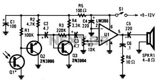
This receiver for amplitude-modulated light signals utilizes a phototransistor Q1 mounted within a parabolic reflector to enhance its range. Any NPN phototransistor is suitable for this application. An emitter-follower configuration using Q2 drives an amplifier stage Q3. The output...
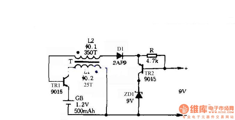
The circuit does not require a separate power switch or transformation to control the switches on the table. It offers advantages such as low power consumption, stability, reliability, and no impact on instrument accuracy. The transformer T in the...
To charge lead-acid batteries, a circuit can be utilized that consists of a current-limited power supply and a flyback converter topology. The described circuit for charging lead-acid batteries employs a current-limited power supply in conjunction with a flyback converter...
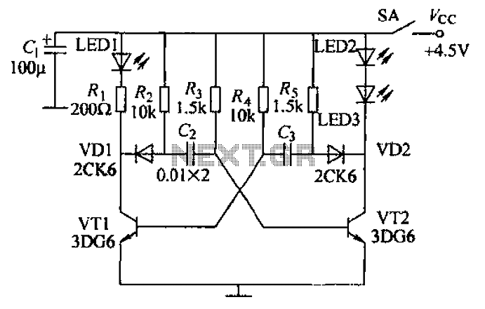
Transistors VT1, VT2, and associated RC components are configured to form a multivibrator. The multivibrator operates with resistors Ra and R4 serving as base bias resistors for VT2 and VT1, respectively. When the switch SA is closed after applying...
The following circuit illustrates a Water Level Detector Circuit Diagram. This circuit is based on the PIC12F683 microcontroller. Features include the ability of the PIC microcontroller to enter a sleep mode. The Water Level Detector Circuit utilizing the PIC12F683 microcontroller...
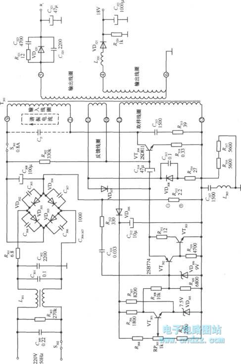
A high voltage switching stabilized voltage supply circuit is illustrated in the diagram. This is the switching power supply for an 80P type color television. It utilizes auto-excitation and a PWM circuit. The output is isolated from the power...