
Basic Multimeter Circuit

The multimeter design incorporates a dual-unit configuration, enhancing versatility in measurement applications. The primary unit features a galvanometer with a maximum deflection of 1mA, which serves as the core measuring element. The inclusion of shunt resistors allows for the extension of current measurement capabilities, enabling the device to handle larger currents without damaging the meter movement. When configuring the shunt, the resistance value must be determined using the formula for parallel resistances, ensuring that the desired current range is achieved while maintaining the meter's accuracy.
For voltage measurements, the multimeter employs series resistors to limit the current flowing through the meter. The resistors are selected based on their high stability and low tolerance, ensuring minimal deviation from the expected readings. The use of an internal battery facilitates resistance measurements, allowing the multimeter to function as an ohmmeter. The range of resistance measurements is extensive, enabling the user to assess components with resistances up to 200,000 ohms, which is particularly useful in troubleshooting and circuit analysis.
The add-on unit expands the multimeter's functionality to include AC voltage measurements. The rectifier within this unit converts AC signals into a DC form that can be accurately measured by the galvanometer. This feature is essential for applications requiring the assessment of alternating currents, such as in power supply testing and electrical installations.
In conclusion, the multimeter's design is a sophisticated integration of shunts, series resistors, and measurement techniques, providing a comprehensive tool for electrical measurements across a wide range of parameters. The careful selection and calibration of components ensure that the multimeter delivers reliable and accurate results, making it an invaluable instrument for engineers and technicians in the field.A number of shunts and multipliers selected by a switch can be used in association with a single basic meter to form a multirange instrument, known as a multimeter. this is capable of measuring volts, current and resistance. A multirange meter can be constructed in two units, the first containing the 0-1mA meter movement with switches to select va
rious shunt and series resistors to give six d. c. current ranges up to 1 amp and eight d. c. voltage ranges up to 1000 volts. An internal battery provides an ohms range readable up to 200, 000 ohms which corresponds with the first division of the meter (0. 02mA) An Add-on unit contains a meter rectifier with associated switched series resistors to give four a.
c. voltage ranges up to 100 volts while additional shunt and series resistors (Ra and Rb) extend the range to 10A and 5Kv. When using the add-on unit the main instument is set to measure 1mA FSD and the add-on unit is connected to its terminals by its lugs.
The series resistors are 1% tolerance high stability types while the shunts are made of lengths of Eureka resistance wire. The wire used on electric fire elements is ideal for the lower value shunts. The values have been calculated for a meter resistance of 60 ohms internal resistance but would need modifying for other values.
In any case, the precise value of each shunt should be adjusted experimentally to give the correct reading against a meter of known accuracy. For example: If a milliammeter of 10 ohms resistance and a FSD of 1mA is to be used to measure 100mA, a shunt must be provided to carry the excess current, that is 100-1 milliamps, i.
e 99mA. Thus the required shunt resistance is: 🔗 External reference
Related Circuits
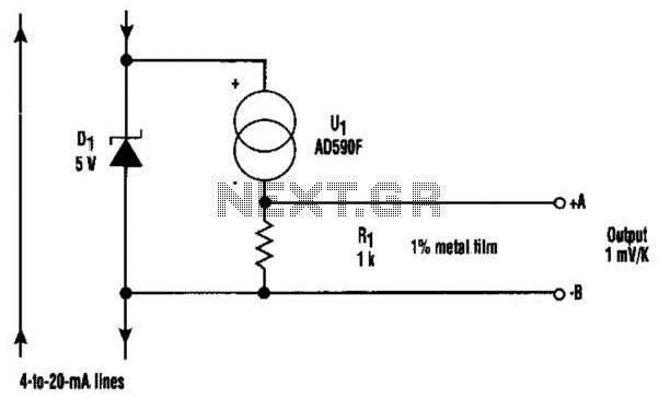
At the core of this circuit is the KTY10 temperature sensor from Siemens. This silicon sensor functions as a temperature-dependent resistor, integrated as one arm of a bridge circuit. A preset potentiometer (P1) is used to balance the bridge...
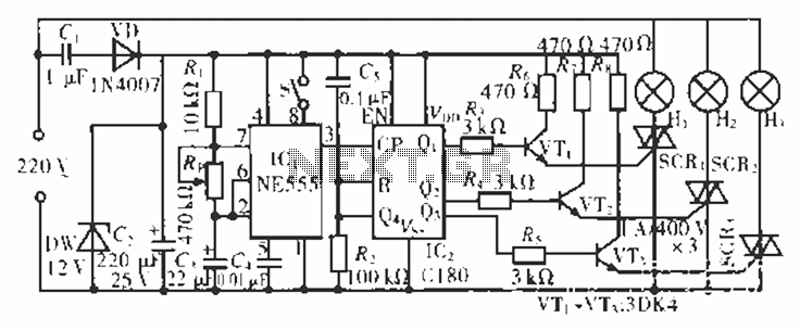
The circuit operates at 220 V AC using a C1 buck converter and a DW regulator. The VD ensures the entire stream is processed, and C2 provides a filtered output of 12 V DC for the voltage supply control...
VOX is a voice-activated switch commonly used with microphones as an alternative to traditional push-button switches. The VOX can be connected to various audio equipment featuring an external speaker for coupling. The activation threshold is adjusted using the volume...

This modem/fax protector can be utilized in telephone-line connections between a PC or a terminal and a remote computer. In this circuit, the surge voltage protectors (SVPs) are rated at 230 V. Additionally, a proper grounding is essential for...
This circuit can be directly connected to CD players, tuners, and tape recorders. It requires the addition of a 10K logarithmic potentiometer (dual gang for stereo) and a switch to accommodate various sources. Proper grounding is crucial to eliminate...
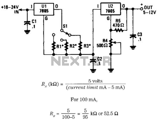
This voltage regulator and current limiter combination can be constructed using two 7805 regulators as illustrated. Resistors R1, R2, and R3 should be chosen to achieve a 5-V drop at the maximum allowable current limit. Switch S1 selects one...