
Cheapest High power LED driver circuit diagram
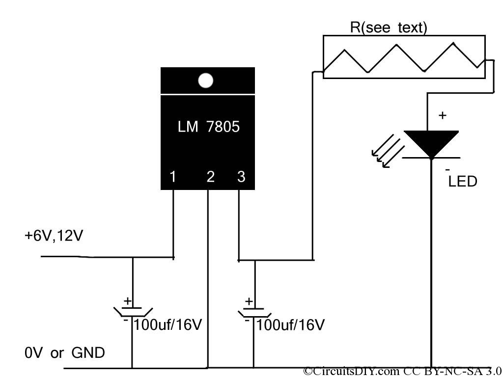
The circuit described is a straightforward high-power LED driver designed for reliability and ease of assembly. The use of the LM7805 voltage regulator provides a stable output voltage of 5V, which is essential for driving high-power LEDs effectively. The forward voltage ratings of the LEDs dictate the necessary voltage drop across the current-limiting resistor, R.
In the case of the 1Watt LED, the voltage drop across the LED is approximately 3.4V. Therefore, the excess voltage that needs to be dissipated by the resistor is 1.6V (5V - 3.4V). The current flowing through the LED is 300mA, allowing for the calculation of the resistor value using Ohm's Law (V = IR). The required resistance can be calculated as follows:
R = V/I = 1.6V / 0.3A = 5.33 Ohms.
Considering standard resistor values, a 5.6 Ohm resistor is selected, which is readily available and meets the power rating requirement of 0.48 Watts. The power rating is calculated using the formula P = I²R, giving:
P = (0.3A)² * 5.33 Ohms ≈ 0.48 Watts.
For the 3Watt LED, the same approach applies. The forward voltage is again approximately 3.4V, leading to a similar calculation for the resistor value needed to limit the current to 700mA. The voltage drop across the resistor would be:
R = 1.6V / 0.7A = 2.29 Ohms.
A standard resistor value of 2.2 Ohms is suitable for this application. The power rating for this resistor is calculated as:
P = (0.7A)² * 2.2 Ohms ≈ 1.08 Watts.
Thus, a resistor rated at 2 Watts is recommended to ensure reliability and longevity in operation. This simple LED driver circuit is advantageous for applications requiring straightforward design and assembly while effectively driving high-power LEDs.If you came here through Google, then you might have seen other circuits too for high power LED driving which consists of much parts, like inductors, op-amps, different regulator IC`s, transistor feedback networks, microcontrollers etc. Those circuits are more efficient than this one but the making expense and difficulty is much more high and so
I am here showing you the simplest high power LED driver circuit. In market, we can get 1Watt and 3Watt LED easily. And the ratings of those 1Watt LEds are Forward Voltage 3. 2V 3. 6V, Forward Current 300mA and for the 3Watt ones, m the ratings are Forward Voltage: VF3. 4V, Forward Current :700mA. Here, for a fixed reference supply, LM7805 regulator I. C which can deliver upto 1Amps of current, and in our cases the max required current is 700ma or 0. 7Amps, so no problem there. And since the resistor R will be eating the extra 1. 6 volts(5. 0-3. 4). So what would be the value of R For 1 watt model, there`s current of 300mA, so the value of the resistor should be 5. 3 Ohms(appx) and wattage should be 0. 48. So a 5. 6ohms 1/2watt general purpose resistor will do the job perfectly. And similarly, for the 3Watt model, the value of R would be 2. 2Ohm 1. 25Watt(or 2Watt). 🔗 External reference
Related Circuits
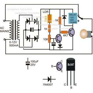
This circuit diagram illustrates a light-activated switch utilizing the National Semiconductor comparator IC LM311 and a light-dependent resistor (LDR). The configuration is based on a voltage comparator circuit centered around IC1. The non-inverting input of IC1 receives a reference...
Just to prove that transistors can also be useful in logic situations; this is a data latch and indicator which also is a data switch and has a bidirectional input/output port which can be read or switched. If the...
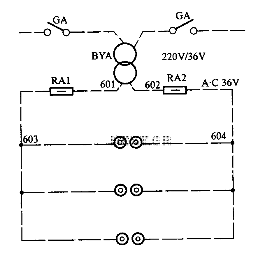
APM-81 lift includes the main circuit, safety circuit, and brake circuit. The APM-81 lift system is designed with a comprehensive electrical architecture that integrates a main circuit, a safety circuit, and a brake circuit, ensuring reliable operation and enhanced safety...
The device circuit operates as illustrated in Figure 11. Power outages are a common occurrence, but in certain situations, maintaining power is critical, such as during ongoing surgeries. The circuit employs a simple design that is fully automated. When...
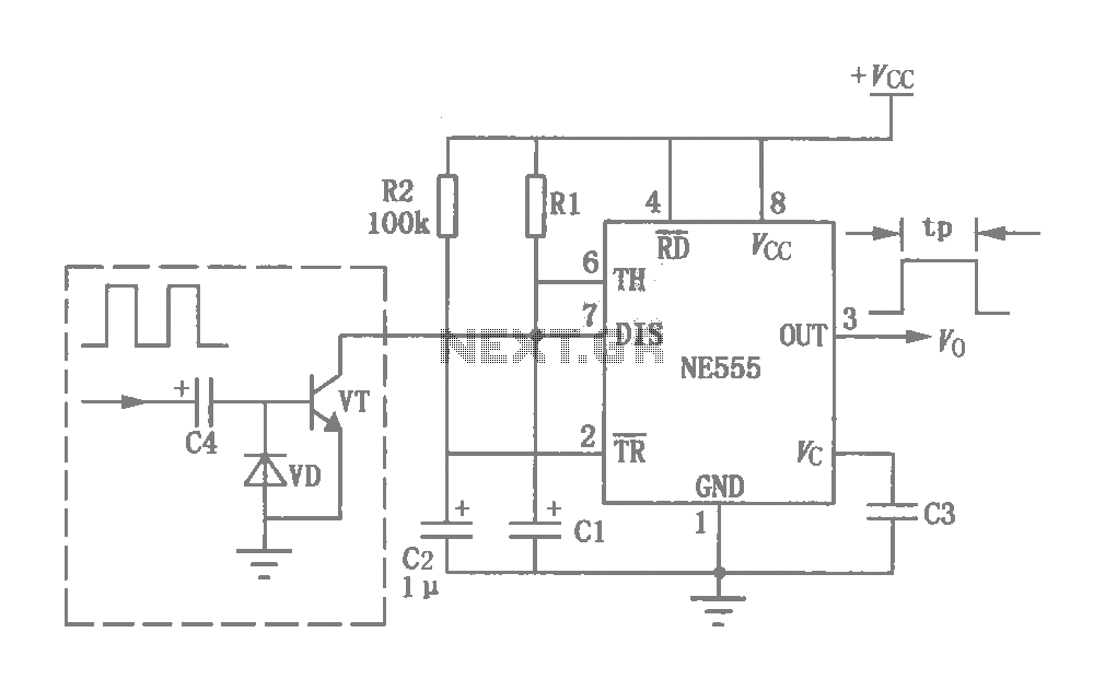
This circuit was originally a type of power-delay control circuit, where the delay time is determined by the timing elements R1 and C1. Additionally, with the inclusion of a "watchdog" circuit, it can be utilized as a monitoring circuit...
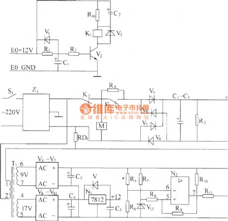
220V (50Hz) alternating voltage passes through the Z1 circuit filter, which filters the signal before sending it to the connection point of the AC overvoltage and undervoltage protection relay K2. During normal operation, the K2 connection point should be...