
Clap Switch Circuit using NE555 timer IC

The clap switch circuit is a practical application of the NE555 timer and the 7474 D flip-flop, showcasing the interaction between sound detection and electronic switching. The NE555 timer is configured in a monostable mode, meaning it generates a single output pulse in response to an input trigger—in this case, the sound of a clap. The output pulse from the NE555 serves as a clock signal for the D flip-flop. The 7474 D flip-flop is designed to toggle its output state with each clock pulse it receives, effectively responding to the sound detected by the NE555 timer.
In operation, the NE555 timer detects a sound (such as a clap) and generates a negative pulse. This pulse is fed into the clock input of the D flip-flop, which is configured to toggle its output state on the falling edge of the clock signal. The first negative edge from the NE555 causes the output of the flip-flop to switch to a high state, while the next negative edge causes it to return to a low state. This toggling action can be used to control a relay, which in turn can switch on or off any connected electrical device, such as a light bulb or other appliances.
The circuit's versatility allows it to be used in various applications beyond just a clap switch, including sound detection systems and automated lighting controls. The relay acts as an interface between the low-power logic of the flip-flop and the higher power requirements of the connected devices, ensuring safe and reliable operation. Overall, this circuit exemplifies the principles of sound detection and electronic control, making it an excellent project for students and electronics enthusiasts.Here is one of the interesting 555 timer circuits to trick your friends while studying electronics in schools. Clap switch circuit is the local name of sound controlled flip flops. This sound controlled light can also be used as sound detection sensors. Flip flops are single bit storage elements. NE555 timer IC is the important part of this circuit . Here NE555 is configured in monostable multivibrator mode and is connected to the clock input of a 7474 D flip flop. The flip flop is connected to work in Toggle` mode. The relay circuit is energized by a 7474 flip flop. You can connect any electrical/electronic device at the output instead of the electrical bulb used here.
Below is the electronic circuit diagram and working of the clap light switch. Output of the 555 is connected to clock input of D-flip flop (IC 7474). It is a -ve edge triggered flip flop. When the Monostable output goes to zero, flop-flop`s output Toggles. That is (For time being consider flip-flop out is zero), for the 1st -ve transition output of the flip-flop goes to high and for the next -ve edge, output will be low. It will continue for successive -ve edges 🔗 External reference
Related Circuits
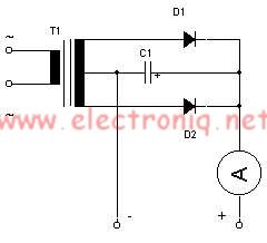
This simple lead-acid battery charger requires a center-tapped transformer (12V 0V 12V) capable of delivering a current of 5 amperes, two diodes, and one capacitor. To charge the batteries, the positive and negative terminals from the charger must be...
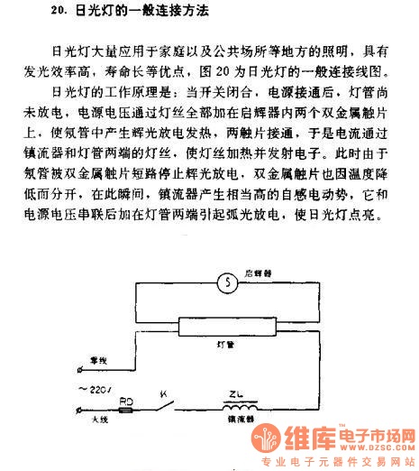
The general connection method for fluorescent lamps is utilized in residential and public lighting applications due to their luminous efficiency and long service life. The general wiring diagram for the lamp is illustrated in Figure 20. The working principle...
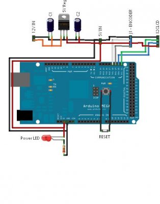
The requirement was to add a digital readout to a manually operated bend roller machine to accurately monitor the amount of material fed into the machine. The readout should be user-friendly, requiring no setup other than initial calibration, and...
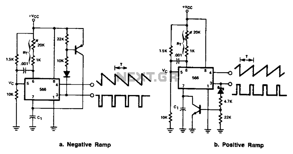
The 566 can be connected to either a positive or negative ramp generator. For a positive ramp generator, an external transistor is driven by the output pin 3. At the end of charging, C1 discharges quickly, allowing for immediate...
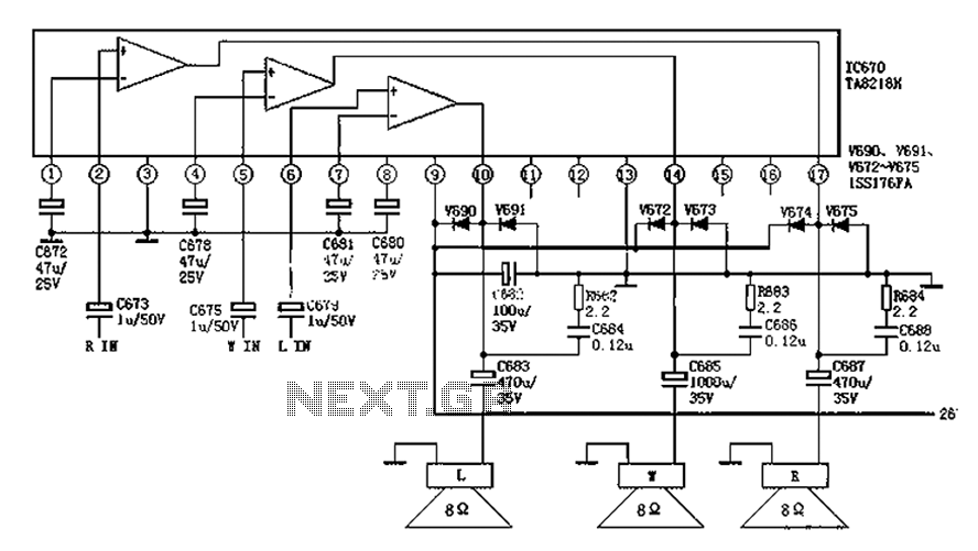
The audio circuit depicted in the figure is commonly utilized in color television systems. The pin functions and reference voltages for the TA8218AH are as follows: Pin 1: 1.9V - inverting input; Pin 2: 2.1V - R-channel audio signal...
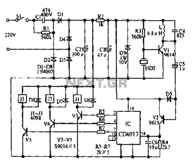
Fans can be controlled remotely with a switch that allows for speed adjustments, and this remote control can also be integrated with other household switches. Its primary feature is the use of a sub-transmission ultrasonic transmitter, which operates without...