
DC motor driver circuit design using LM628 LM629 dedicated motion-control processors
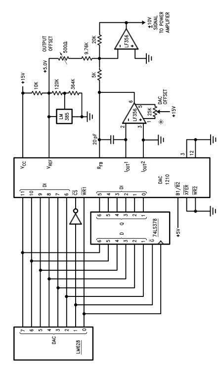
The circuit utilizes the LM628 and LM629 processors, which are specifically designed for motion control applications, making them suitable for managing both DC and brushless DC servo motors. The integration of the LM12 high-power operational amplifier within the motor driver circuit allows for efficient control of motor functions, providing the necessary power handling capabilities.
In the schematic, the gain-setting resistors R1 and R2 play a critical role in determining the overall gain of the amplifier circuit. By carefully selecting their values, the desired amplification can be achieved while ensuring that the output remains within the limits of the power supply. The specified gain of 2.2 is optimal for maintaining linearity in the output, particularly under conditions that approach saturation. This is crucial because exceeding the linear range can lead to distortion and inefficiencies in motor control.
The power supply configuration of ±30V is essential for achieving the required output levels, allowing the circuit to deliver ±22V at the output. This voltage range is particularly advantageous for applications requiring high torque and precise control over the motor's performance. The non-linear characteristics of the amplifier when saturated necessitate careful design considerations to ensure that the system remains stable and responsive during operation.
Overall, this motor driver circuit, leveraging the capabilities of the LM628, LM629, and LM12, presents a robust solution for various servomechanism applications, facilitating effective control of DC and brushless DC motors with high precision and reliability.Using the LM628 LM629 dedicated motion-control processors can be designed a variety of DC and brushless DC servo motors, and other servomechanisms applications. The power path of this electronic project, motor driver is based on the LM12 high power operational amplifier that can be used in some other power applications like : motor controller,
audio amplifiers or some other power applications. Resistors R1 and R2 should be chosen to set the gain to provide maximum output voltage consistent with maximum input voltage. This circuit provides a gain of 2. 2, which allows for amplifier output saturation at ±22V with a ±10V input, assuming power supply voltages of ±30V.
The amplifier gain should not be higher than necessary because the system is non-linear when saturated, and because gain should be controlled by the LM628. 🔗 External reference
Related Circuits
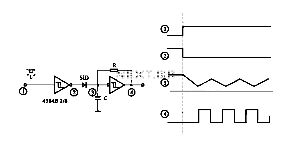
The circuit generates a controlled pulse signal. When a high pulse signal is applied to the input terminal O (start), the output pulse signal is activated. Conversely, when a low signal is received at the input terminal O (stop),...
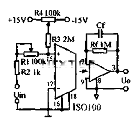
An adjustable gain test is conducted in preparation for an isolation amplifier circuit, utilizing the optical coupling isolation amplifier ISO100. This adjustable gain can form part of a test device for the isolation amplifier. The circuit gain can be...
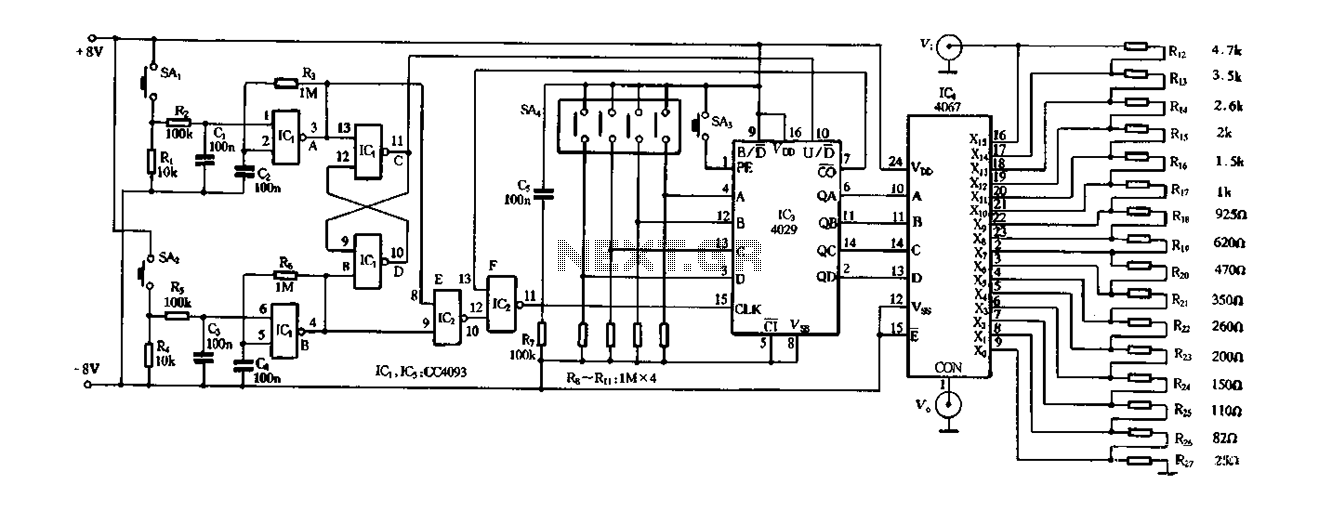
Figure 4-14 illustrates a digital integrated circuit featuring 16 preset potentiometers for Siniperca electronic circuits. The circuit comprises three main components: an input controller, a presettable counter, an analog electronic switch, and a resistor network. It includes a push-button...
Two-Tone Siren Circuit Schematic Using One IC. This circuit is designed for children's entertainment and can be installed on bicycles, battery-powered cars, motorcycles, as well as models and various games and toys. It includes a switch (SW1) for operation. The...
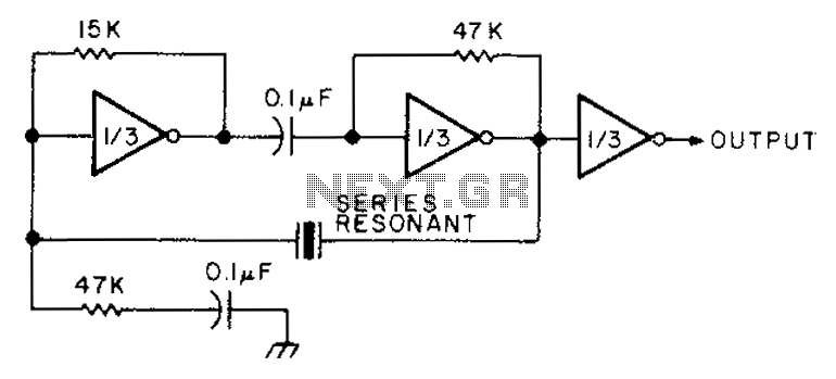
The circuit diagram illustrates the connection of all three components of the series resonant crystal and triple CD4049 inverter. The supply voltage range is between 3 to 15 volts, making it suitable for various applications. This design is compact...
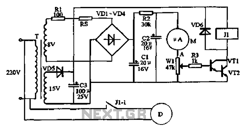
An automatic humidifier can be utilized for humidity control in households, hatcheries, poultry farms, or juvenile poultry houses. When the humidity level falls below 50%, the automatic humidifier activates to maintain a specific humidity level that is beneficial for...