
F6DQM Software Interfacing you computer

The provided information indicates that the pc_tx.bmp file contains visual representations or diagrams that illustrate various methods for interfacing transceivers with a computer system. These connections are intended for use with SIMPLEX software, which is likely designed for communication or data transmission purposes in simplex mode, where communication occurs in one direction at a time.
To implement these connections effectively, it is essential to consider the following components and their roles:
1. **Transceiver**: A device that can both transmit and receive signals. The selection of the transceiver should be compatible with the frequency and modulation requirements of the application.
2. **Computer Interface**: This may involve using USB, serial, or other forms of communication protocols to establish a link between the transceiver and the computer. The interface should be capable of handling the data rates required by the SIMPLEX software.
3. **Power Supply**: Ensure that the transceiver is powered adequately, as insufficient voltage or current can lead to malfunction during operation.
4. **Signal Conditioning**: Depending on the distance and medium of communication, additional components such as filters, amplifiers, or isolators may be necessary to maintain signal integrity.
5. **Software Configuration**: The SIMPLEX software will require proper configuration to recognize the transceiver and manage the data flow. This may involve setting parameters such as baud rate, data bits, stop bits, and parity settings.
6. **Testing and Validation**: After establishing the connections, it is crucial to test the setup to ensure that data transmission and reception are functioning as intended. This may involve using diagnostic tools or software to monitor the communication process.
By following these guidelines and utilizing the examples provided in the pc_tx.bmp file, users can effectively connect their transceivers to a computer for optimal performance in SIMPLEX software operations.More examples to connect your transceivers to the computer for SIMPLEX software operations are described in the pc_tx. bmp file that is included in the simplex. zip file. 🔗 External reference
Related Circuits

A and B are two common contacts, along with an outline drawing and pin definitions. C refers to the shape of the infrared emission tube, including its pin definition and schematic symbol. CD4069 provides the pin definitions for the...
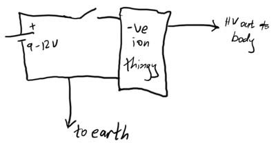
This article demonstrates how to create a simple yet effective static electricity generator. This device enables the user to carry a constant static charge on their body and discharge it onto anything grounded or of opposite polarity. The generated...
Standard serial interfacing of a microcontroller (TTL) with a PC or any RS232C standard device requires a TTL to RS232 level converter. A MAX232 is used for this purpose. It provides a 2-channel RS232C port and requires external 10µF...
This circuit is utilized in RS-232 serial interface and current loop circuit applications. It converts voltage signals into a 20mA current signal, with a maximum transmission rate of 1200 bits per second. The CCD IC1 and transistor T1 form...
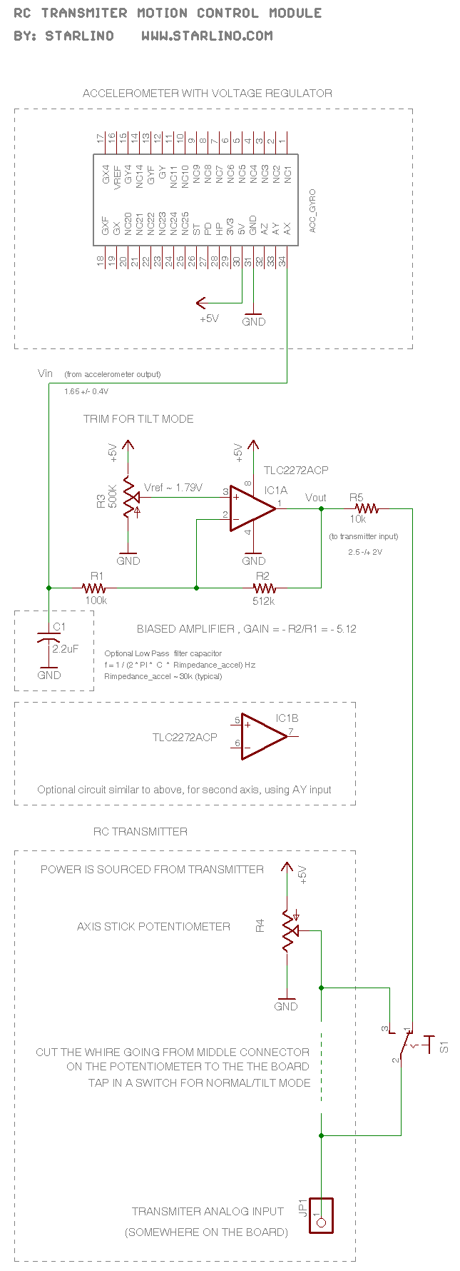
The RC transmitter utilizes a potentiometer for each axis, functioning as a voltage divider that outputs a voltage of 0.5V, with the middle position corresponding to 2.5V. This voltage is sent to the analog input, which is converted into...
In various electronic applications, it is necessary to switch or control high voltages or high currents. In such instances, electromagnetic or solid-state relays may be utilized. For example, these relays can control home appliances using low-power electronic circuits. An...