LCD projector multi-function controller circuit diagram
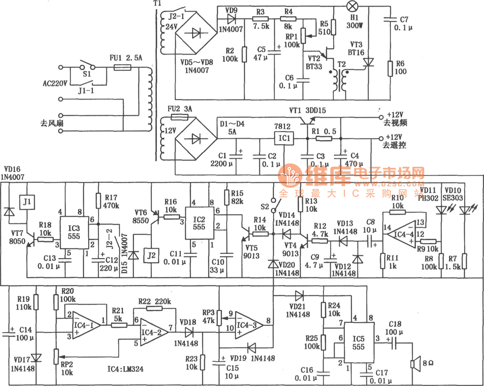
In the production of LCD projectors, the primary factor threatening the lifespan of the LCD screen is the temperature generated by halogen lamps. The multi-function controller designed by this circuit is highly effective for protecting liquid crystal projectors. The circuit for the LCD projector multi-function controller includes components such as VD1 to VD4, IC1, C1, and VT1.
The LCD projector multi-function controller circuit is engineered to monitor and regulate the temperature of the halogen lamp, thereby enhancing the longevity and performance of the LCD screen. The core components of the circuit include diodes (VD1 to VD4) that serve as protection elements to prevent reverse polarity and voltage spikes, ensuring the integrity of the circuit.
The integrated circuit (IC1) acts as the central processing unit, managing the inputs from temperature sensors and controlling the output signals to the other components in the circuit. Capacitor C1 is used for filtering and stabilizing the voltage supply, contributing to the overall reliability of the circuit operation.
Transistor VT1 functions as a switch that regulates the power supply to the halogen lamp based on the temperature readings from the sensors. When the temperature exceeds a predetermined threshold, the controller reduces the power to the lamp, thereby lowering its temperature and preventing damage to the LCD screen.
This multi-function controller circuit is crucial for maintaining optimal operating conditions within the projector, ensuring that the LCD screen remains protected from excessive heat. Proper implementation of this circuit can significantly extend the operational life of LCD projectors, making it an essential component in their design and production.In the production of LCD projector, the main factors of the threatening life of LCD screen is the temperature of halogen. The multi-function controller made by this circuit is very effective for the protection of liquid crystal projector.
The LCD projector multi-function controller circuit is shown as below. The circuit composed of VD1 ~ VD4, ICl, C1, VTl.. 🔗 External reference
