
LED Flasher 2-Transistors circuit diagram
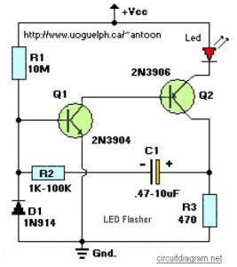
This circuit utilizes a high-brightness red LED, which is critical for visibility in applications such as alarms. The design allows for flexibility in component selection, particularly in the resistors used, enabling the circuit to be adapted based on available materials. The resistor R3 is essential for controlling the LED's brightness; a value of 470 ohms is standard, but a lower value such as 390 ohms can be used to increase brightness at the cost of higher current draw.
The timing characteristics of the flashing LED are determined by the combination of resistor R2 and capacitor C1. The time constant, defined as τ = R2 * C1, dictates how long the LED remains on and off, with the overall flashing frequency being approximately 1/(3*τ). This allows for customization of the flash rate depending on the desired application.
Transistor Q1 functions as a switch, controlling the operation of Q2, which drives the LED. R1 serves to bias Q1, ensuring that it operates in the correct region of its transfer characteristics. If the circuit does not oscillate as intended, adjustments to R1 or R2 may be necessary to achieve the desired behavior.
Diode D1 plays a critical role in managing the feedback to Q1, ensuring stable operation and allowing for higher duty cycle performance. In scenarios where low power supply voltages are utilized, such as 6 to 9 volts, or when a lower duty cycle is acceptable, D1 can be excluded from the circuit, simplifying the design while maintaining functionality.
Overall, this circuit exemplifies a straightforward yet effective design for creating an attention-grabbing LED flash, suitable for various applications with adjustable parameters to accommodate different LEDs and operational requirements.This circuit will flash a bright or high-brightness red LED (5000 mcd). Great for fake car alarm or other awareness getting equipment. Component values aren`t significant, attempt anything else first from the junkbox. Obviously, the 470 ohm resistor (R3) determines the LED`s brightness and limits the current flow to around 20mA. R3 value of 390 ohm can also be implemented as a save value. If you determine to go with a green or yellow led, which take extra current, you might wish to change the 470 ohm with an proper value. Flash rate is determined by R2 and C1 and it is approximately three time constants (3*R2*C1). R1 provides bias to Q1 which should be low enough not to saturate Q2 with the capacitor disconnected.
When the circuit does not oscillate, R1 may be too low or R2 too high. D1 allows for higher duty cycle operation and limits the feedback at the base of Q1 to -0. 7 volts. D1 might be ommited for low supply power like 6 9V and low duy cycle operation. 🔗 External reference
Related Circuits

This design is for a thermometer circuit that utilizes the LM35 integrated circuit (IC) as a temperature sensor. It is a straightforward circuit that allows for the measurement of room temperature using a digital voltmeter or any voltmeter capable...
A modulated current is supplied by the integrated rotational speed sensor KMI 15/x. This current signal needs to be converted into a ground-referenced voltage signal. The KMI 15/x sensor operates by generating a modulated current proportional to the rotational speed of...

An audio power amplifier circuit for a 3-watt stereo amplifier using the MAX 7910 IC is explained below. The audio power amplifier circuit utilizing the MAX 7910 IC is designed to deliver a maximum output power of 3 watts per...
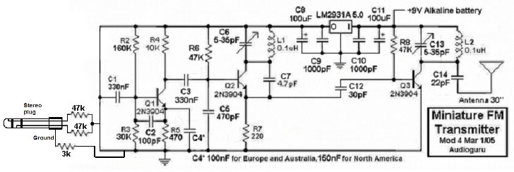
This small FM transmitter can be modified to replace the microphone with an audio jack, allowing it to connect to an MP3 player for audio playback through car audio systems. The design is straightforward and intended for a short...
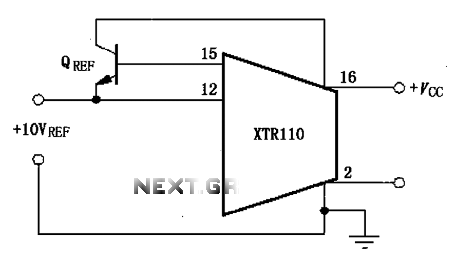
The XTR110 features an internal voltage reference that can output a current of 10mA. By incorporating an external NPN transistor, designated as QREF, the output current capability can be increased. When the VCC voltage reaches 40V, a 2N3055 transistor...

A small (2 to 3 meters) neon electronic transformer circuit diagram is provided below. The described circuit diagram is intended for use with neon lighting systems, specifically those requiring a transformer to operate efficiently within a range of 2 to...