
Make-Yourself ATmega32 Starters Kit with LCD I2C SPI RTC ADC interfaces
The ATmega32 microcontroller is a versatile and powerful component widely used in embedded systems. It operates at a maximum clock speed of 16 MHz and supports multiple communication protocols, making it suitable for various applications. The integration of 32kB flash memory allows for substantial program storage, while the 1KB EEPROM provides non-volatile data storage, ideal for retaining configuration settings or calibration data.
The kit's design incorporates an LCD interface, which facilitates user interaction by displaying information and enabling user inputs. The contrast adjustment feature enhances visibility under different lighting conditions. The inclusion of an RS232 port allows for serial communication with a PC, enabling data exchange and monitoring of the microcontroller's operation.
The analog inputs connected to the ADC enable the measurement of varying voltage levels, making the kit suitable for sensor interfacing and data acquisition applications. The Real-Time Clock (RTC) IC DS1307 is crucial for timekeeping, providing accurate time and date information, with battery backup ensuring continued operation during power outages.
The user interface is enhanced by four general-purpose keys that can be programmed for various functions, while the two interrupt keys allow for immediate response to specific events, improving the kit's interactivity. The presence of an LED can be utilized for status indication or debugging purposes.
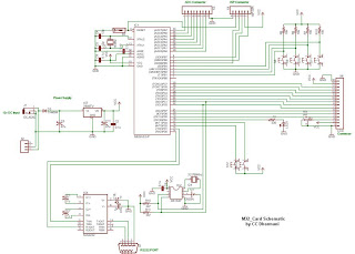
The home-made PCB, created using the etching method with Ferric Chloride, demonstrates a practical approach to prototyping and circuit design. This method allows for the customization of the circuit layout to meet specific project requirements, making it an invaluable skill for electronics enthusiasts and professionals alike. For those interested in PCB fabrication, tutorials and resources are available online to guide users through the process from layout design to etching and finishing.Here is my home-made kit of ATmega32 microcontroller interfacing. The ATmega32 controller is rich with features like onboard 32kB in-System programmable flash, 1 KB EEPROM, 2KB SRAM, 10bit ADC (8 channel), SPI bus inteface, TWI (compatible with I2C bus) interface, an USART, analog comparator, etc. That`s why I`ve selected it to load my kit with al l those features. This M32 card is having an LCD inteface with contrast adjustment, an RS232 port for connecting with PC, a connector for 8 analog voltage inputs to measure by ADC, a Real Time Clock IC DS1307 from maxim with battery back-up, four general purpose keys, two keys for generating interrupts and an LED. The PCB is completely home-made, using the etching technique with the Ferric Chloride chemical. If you want to know how to make a PCB yourself from your layout, visit following webpage, it`s really helpful:
🔗 External reference
Related Circuits
This kit includes fully illustrated instructions and a circuit schematic. Components are adequately spaced for easy assembly and value identification on the board. The circuit board features silk-screened outlines for component placement, and the circuit pads on the solder...

LCD2USB is an open source/open hardware project. The goal of LCD2USB is to connect HD44780 based text LCD displays to various PCs via USB. LCD2USB was meant to be cheap and to be made of easily available parts. It...
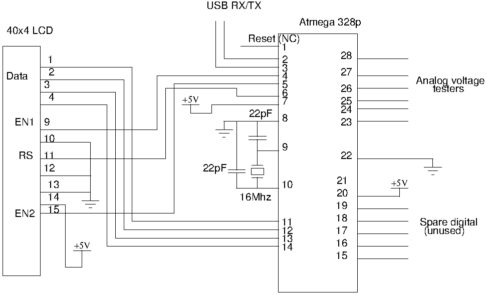
Drive a four-line LCD panel using an Arduino. The project initially aimed to control the LCD for displaying arbitrary information but evolved to include functionalities such as timekeeping, EEPROM read/write operations from the Atmel 328p, and voltage measurement. Multiple...
The resistor between basis and collector (around 47k) is to be individually set according to transistor characteristics. Without PIC in socket at the collector should be 2.5 V. The circuit described involves a transistor configuration where a resistor, typically valued...
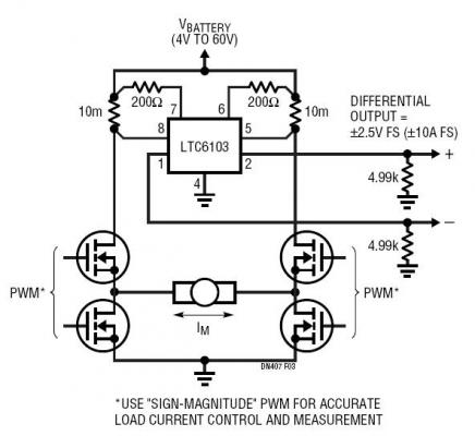
The dual outputs of the LTC6103 can be utilized independently for overload detection or combined as a differential pair to provide a bidirectional signal to an analog-to-digital converter (ADC). A typical circuit for a generic H-bridge application is illustrated....
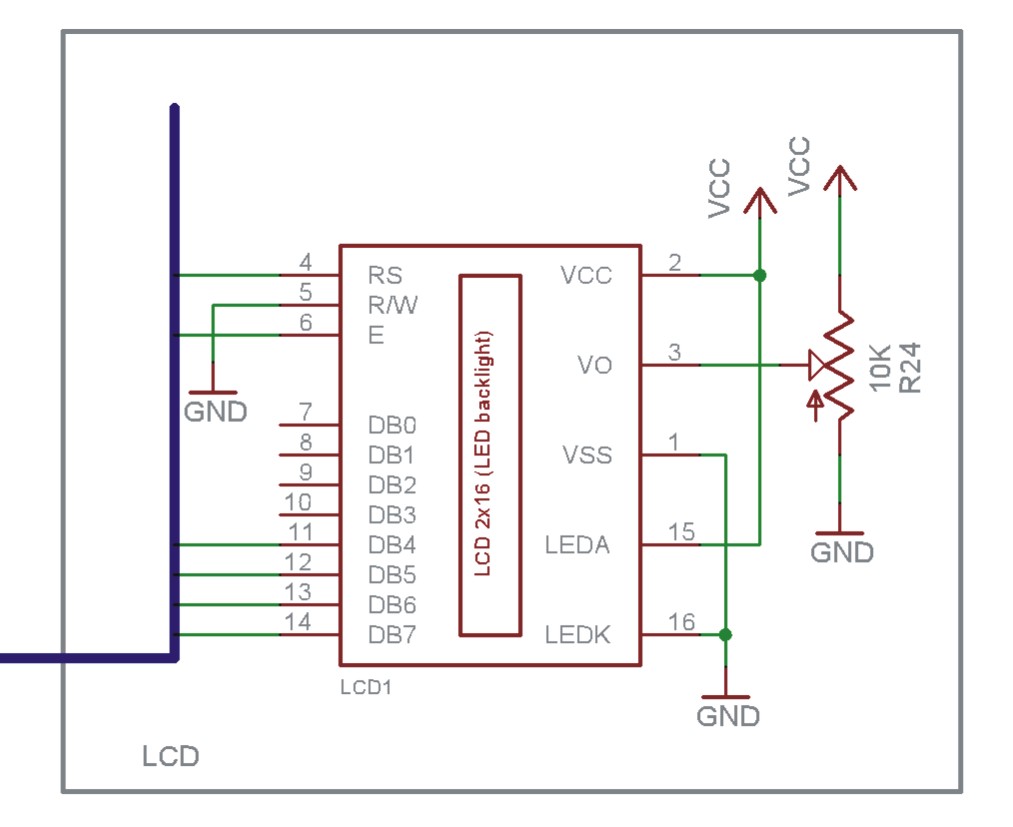
The EN line is referred to as 'Enable'. This control line is utilized to indicate to the LCD that data is being sent. To transmit data to the LCD, the program must ensure that this line is low (0),...