
Metal Detector Circuit with Diagram and Schematic
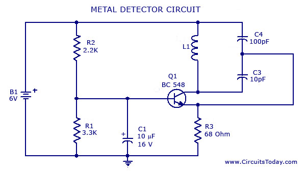
The metal detector circuit utilizes a single transistor in conjunction with a radio receiver to detect the presence of metallic objects. The core of this design is based on the Colpitts oscillator, which is known for its simplicity and effectiveness in generating oscillations at radio frequencies.
In this schematic, the transistor acts as the main amplifying component, forming the oscillator circuit with the inclusion of capacitors and an inductor, which are essential for determining the oscillation frequency. The Colpitts configuration employs two capacitors in series with an inductor, creating a resonant tank circuit. This tank circuit resonates at a specific frequency that can be tuned to detect various metal types based on their conductive properties.
When a metallic object comes into proximity of the detector, it alters the inductance of the coil, resulting in a change in the frequency of oscillation. This frequency shift can be detected by the radio receiver, which is tuned to the oscillator's frequency. A simple audio output can be generated, indicating the presence of metal.
The circuit requires a power supply, typically a battery, which powers the transistor and the radio. Careful selection of the transistor is crucial, as it must have sufficient gain to amplify the weak signals generated by the oscillator. Additionally, the choice of the inductor and capacitors will affect the sensitivity and range of the metal detector.
Overall, this metal detector project exemplifies a practical application of basic electronic components and principles, making it an excellent choice for educational purposes or hobbyist experimentation.A simple metal detector circuit diagram and schematic using a single transistor and a radio. This metal detector/sensor project is easy to make and is an application of Colpitts oscillator.. 🔗 External reference
Related Circuits

The automatic emergency light circuit has the following features: 1. When the mains supply (230V AC) is available, it charges a 12V battery up to 13.5V, after which the battery is disconnected from the charging section. 2. When the...
The purpose of this timer is to disconnect the compressor circuit and connect a resistive heating element located near the evaporator at regular time intervals. The defrost heater is controlled by a thermostat and is used to melt any...

Figure 1-122 is a dedicated high-fidelity surround sound processing integrated circuit (IC) TDA3810 circuit that manages surround sound. The stereo signal is processed through input coupling capacitors C1 and C2. The internal buffer amplifier handles the left and right...
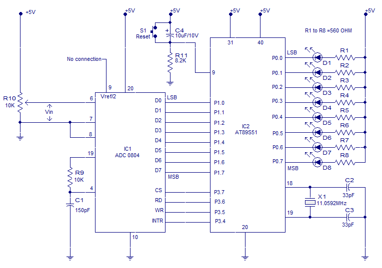
Interfacing ADC to 8051 microcontroller. ADC0804 is interfaced to microcontroller AT89S51. Complete circuit, theory and program in assembly language. The interfacing of an Analog-to-Digital Converter (ADC) with a microcontroller is a critical aspect of embedded systems design, particularly when analog...
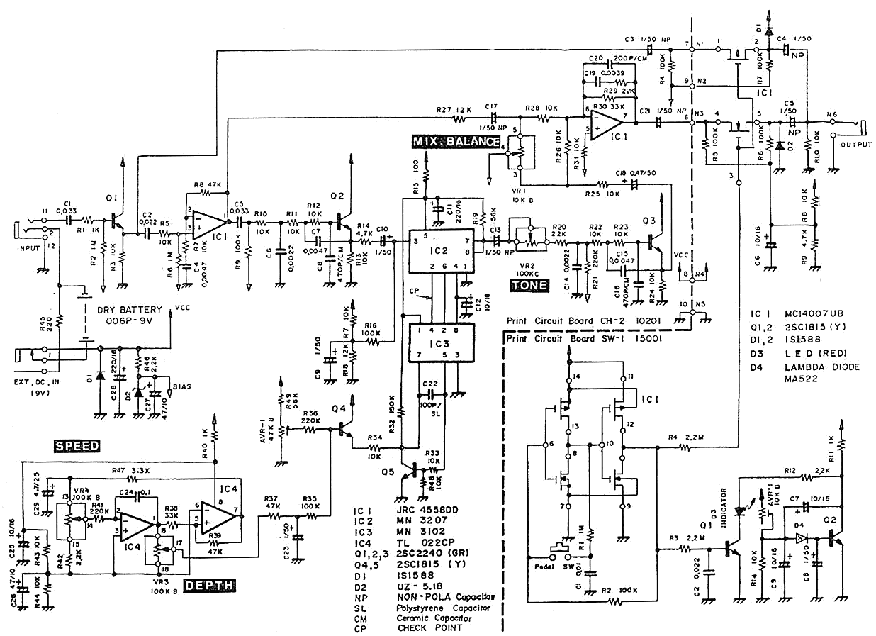
The Pearl CH-02 Chorus is a discontinued pedal known for its exceptional sound quality. It features four knobs: DEPTH, SPEED, TONE, and MIX BALANCE. The TONE knob specifically adjusts the tone of the effect sound, while the MIX BALANCE...

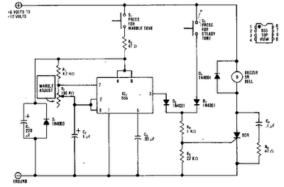
A schematic diagram for a broadband QRP SWR metering circuit intended for use in a QRP antenna tuner. The circuit allows the user to press a momentary DPDT switch to observe an LED indicator while adjusting the capacitors of...