
Microchip PIC Programmer ICSP Circuit Guide
The circuit for In-System Programming (ISP) is designed to ensure compatibility and functionality across various PIC microcontroller models. The circuit's architecture should include a robust power management system to accommodate the varying voltage requirements of different PIC devices. The use of a diode on the VDD line serves not only as a protective measure but also as a voltage clamp, preventing backflow of current that could potentially damage sensitive components.
The inclusion of resistors on the MCLR/VPP pin is critical for ensuring stable operation during programming sessions. The selection of resistor values directly influences the timing and responsiveness of the programming process. It is essential to adhere to the recommendations provided for resistor values to mitigate the risk of premature code execution.
Furthermore, the careful consideration of capacitor values on the MCLR and programming lines is paramount. While capacitors can help filter noise, their values must be selected judiciously to avoid interference with the programming sequence. The recommended maximum capacitance of 1nF for the programming lines ensures that the circuit remains responsive and does not inadvertently disrupt the programming signals.
For applications where the Clock and Data lines cannot be dedicated to ICSP, implementing series resistors is a prudent method to isolate these lines from potential interference. The use of a multiplexer, such as the 4053, may be warranted in more complex setups where additional isolation is necessary to maintain signal integrity.
In conclusion, the design of the ICSP circuit must take into account the specific requirements of the target PIC microcontroller, including voltage levels, signal integrity, and component selection. By following the outlined recommendations, a reliable and effective programming interface can be achieved, ensuring successful communication between the programmer and the target device.Microchip do not recommend any particular circuit for ICSP programming. There are diagrams for different tools, such as Pro Mate and PICKit2 with similar circuitry but slight variations. In some schematics, their suggested resistor values are too small, in our opinion, and can cause problems with programmers, even Microchip ones.
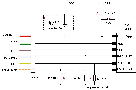
Kanda have developed a recommended In System Programming circuit that will work effectively with our PIC programmer range, and other PIC programmers. This circuit is shown in the diagram below. Please read the notes that describe the circuit and explain the effect of extra components such as capacitors.
Kanda programmers are designed to provide 3. 3V or 5V to the target circuit, but some other ICSP programmers always supply 5V. If your circuit operates at a lower voltage than the programmer, then the diode shown on VDD should be fitted to protect the rest of the circuit. A series resistor may be acceptable instead of the diode in some cases. MCLR/VPP pin needs a resistor to VDD. A minimum of 1K should work but 10K is better. PIC16F devices with only VDD first ICSP entry (PIC16F8x/87x/7x/7x7) should be fitted with a 4K7 resistor as a minimum to reduce the possibility of code running before VPP rises.
Supervisory circuits or push buttons on MCLR should be isolated from the VPP voltage, by placing them on the VDD side of the resistor or by fitting a Schottky diode on this line as per note 1. The 100nF capacitor shown on MCLR/VPP pin is optional for HVP but we do recommend that a capacitor is fitted to avoid glitches on MCLR.
100nF is the maximum value, and we recommend something smaller. Larger capacitors may prevent the PIC from entering HVP mode. Do not fit for LVP mode. If possible, Clock and Data lines should be dedicated to ICSP but where this is not possible, the application circuit should be isolated from the data and clock lines with series resistors, above 10K. This is especially important if either of these lines forces the pin as an input or output. In exceptional cases, series resistors may not be sufficient and a 4053 multiplexer or similar circuit should be used.
Capacitors on these programming lines should be avoided if at all possible. If they are needed, for noise immunity for example, then the maximum capacitance that all programmers can handle is 1nF, although some are better. Kanda Handheld PIC Programmers will provide 3. 3V or 5V VDD to target PIC microcontroller circuits. The target circuit can be powered or unpowered. This can be user selected for most PIC microcontrollers but it is fixed to 3. 3V for J type PIC microcontrollers and LF parts that can be damaged by 5V. The high Voltage programming voltage (VPP) is set to 12V for most PIC devices but is automatically set to 9V for PIC18F K type and newest PIC16F PIC microcontrollers.
🔗 External reference
Related Circuits
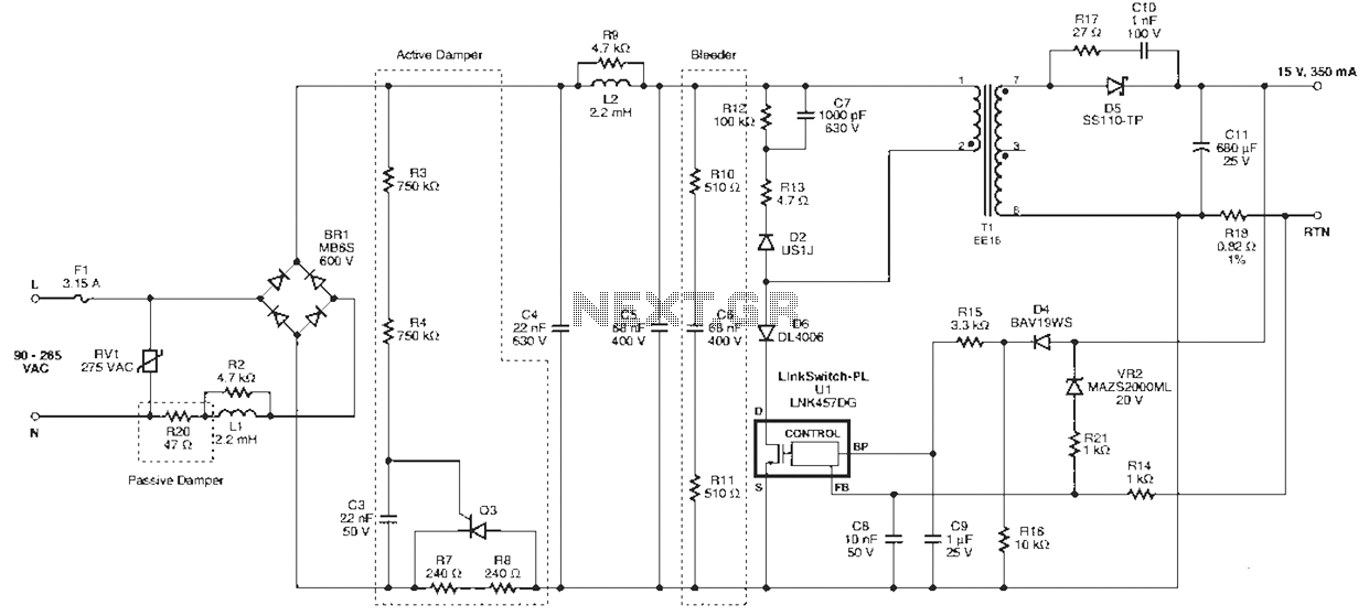
Power Integrations' DER322 reference design employs the LinkSwitch-PL family of LNK460VG devices. This design represents the industry's first alternative 100W A19 incandescent LED driver utilizing a single-layer PCB. It is characterized by low cost, minimal component count, and compact...

The transmitter is constructed on a Printed Circuit Board (PCB). This board incorporates track inductors for L1, L2, and part of L3. The section surrounding Q1 functions as the oscillator section, with the oscillation frequency determined by L1, C4,...
The standard Class AB audio power amplifier allows for direct coupling of the amplifier's output to speakers. This is beneficial as it eliminates capacitors or transformers that could compromise sound quality. The speakers are connected directly to the amplifying...
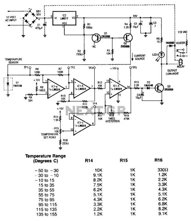
The LM35 temperature sensor outputs 10 mV/C for each degree Celsius above 0°C. At 20°C, the output voltage is calculated as 20 × 10 = 200 mV. The circuit consumes minimal power. Additionally, the load resistance should not be...
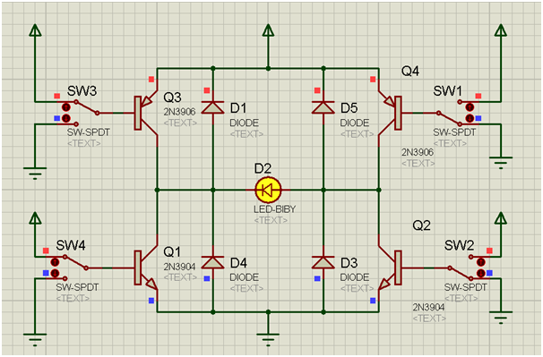
An H-bridge is a circuit configuration that enables the application of voltages in both directions. It permits higher voltage and current to be applied to the load while controlling the direction using a low voltage signal. The accompanying diagram...
The controller consists of a liquid level sensor, a trigger controller, and a step-down rectifier circuit. The water level detection poles labeled a, b, and c form a bias circuit, functioning as a water level detector with components W1,...