
Microphone Mute circuit
The modification to the Kenwood TS-440S microphone is designed to enhance the usability of the device during digital mode operations. The core of the modification involves a simple circuit that effectively mutes the microphone when not in use, preventing unwanted background noise from being transmitted.
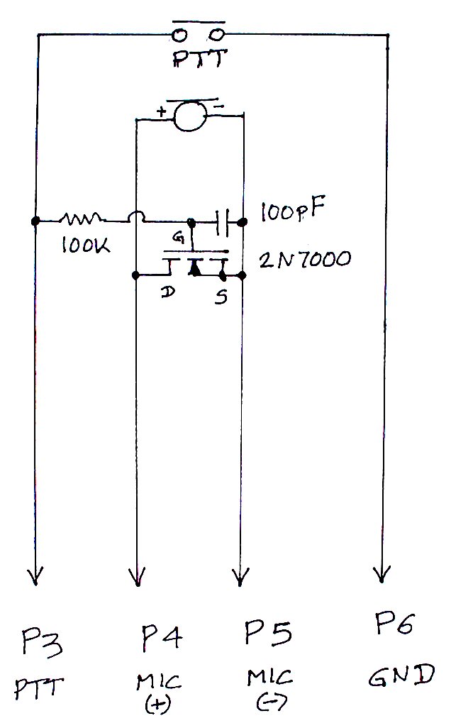
The schematic includes three key components: a resistor, a capacitor, and a small signal MOSFET. The resistor is typically used to limit the current flowing through the circuit, protecting sensitive components from potential damage. The capacitor serves to filter out any high-frequency noise, ensuring that only the desired audio signal is passed through. The small signal MOSFET acts as a switch, controlling the flow of audio to the transmitter.
In terms of implementation, the components can be discreetly housed within the microphone casing. This not only preserves the aesthetic of the microphone but also ensures that the modification does not interfere with the microphone's original functionality. The installation process involves careful soldering of the components to the appropriate points on the microphone's internal circuit board.
When the PPT key is pressed, the MOSFET is activated, allowing audio signals to pass through to the transmitter. When the key is released, the MOSFET turns off, effectively muting the microphone and preventing any extraneous sounds from being transmitted. This modification allows for seamless transitions between digital and voice modes without the need to frequently disconnect the microphone, thus enhancing the overall user experience.
This modification is particularly useful for operators who frequently switch between different modes of operation, as it eliminates the hassle of unplugging and replugging the microphone. Overall, the modification contributes to a more efficient and enjoyable operating environment for users of the Kenwood TS-440S radio.The TS-440S, like probably a number of other radios, does not mute the microphone while you are using the rear audio connector for digital modes. So, unless you unplug the microphone each time you want to use the digital modes, shack noises will get on your signal while you transmit.
Here is the schematic of the simple modification I made to my st ock Kenwood microphone so I do not have to unplug it from the TS-440 while I operate in the digital modes. With this modification, I can leave the microphone plugged in at all times, knowing that unless I depress the PPT key on the microphone, no audio will go to the transmit circuits.
I was able to install the three components (a resistor, a capacitor and a small signal MOSFET, any similar part will work) inside the microphone case, with room to spare. 🔗 External reference
Related Circuits
This is a straightforward and effective LED circuit that can be powered directly from an AC mains supply ranging from 100 volts to 230 volts. The circuit can serve as a mains power indicator or a night lamp. Resistors...
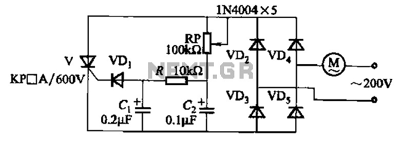
The circuit illustrated in Figure 3-11 employs a unidirectional thyristor control mechanism. An adjustable potentiometer, designated as RP, is utilized to continuously modify the motor speed. The circuit utilizes a unidirectional thyristor, also known as a silicon-controlled rectifier (SCR), which...
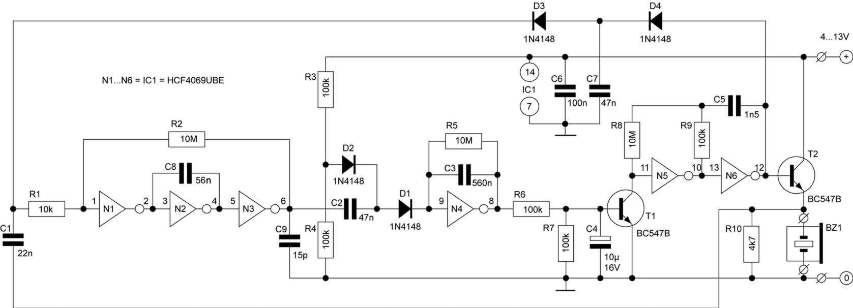
Picture a morning where you are anxiously waiting for the bus to work, only to realize that you cannot find your keys. If this scenario occurs often, this circuit is designed for you. A simple press of a button...
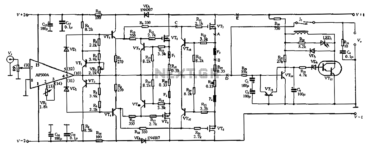
The CPI is a 100W DC super power amplifier circuit based on the AP500. It features a parallel push-pull amplifier output stage composed of transistors VT5, VT6, and VT7 to enhance output power. The circuit's output power is low...
The circuit of automatic emergency light presented here has the following features: 1. When the mains supply (230V AC) is available, it charges a 12V battery up to 13.5V and then the battery is disconnected from the charging section....
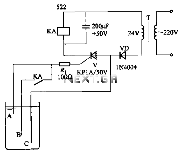
The circuit depicted in Figure 11-14 utilizes a unidirectional thyristor within liquid level automatic control systems. It incorporates electrodes that serve as sensing elements for detecting the level of water or other conductive liquids. The circuit features a current...