
Keys Finder circuit

This circuit functions as a key finder, utilizing a combination of sound and light indicators to assist in locating misplaced keys. It typically consists of a small microcontroller, a speaker or buzzer, and an LED light, all integrated into a compact housing that can be easily attached to a keychain.
When the user presses a designated button on a remote control or a mobile application linked via Bluetooth, the microcontroller activates the buzzer, emitting a loud sound to signal the location of the keys. Simultaneously, the LED light flashes, providing a visual cue that can be particularly useful in low-light environments.
Power for the circuit is usually supplied by a small lithium coin cell battery, ensuring a lightweight design while maintaining sufficient energy for extended use. The circuit may also include a power-saving feature that puts the microcontroller into a low-power sleep mode when not in use, thus prolonging battery life.
The overall schematic design includes connections for the microcontroller to the buzzer, LED, and power supply, along with any necessary resistors or capacitors to stabilize the circuit operation. This user-friendly and efficient solution is ideal for individuals who frequently misplace their keys, offering peace of mind and convenience in daily routines.Imagine that is morning, you barely anticipate the bus for work and you can`t find your keys. If you suffer from this situation frequently, this circuit is ideal for you. A fizzle is the only thing you have to do. The overall circuit is small enough to attach it to your keys.. 🔗 External reference
Related Circuits
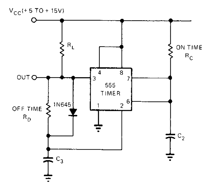
The 555 timer circuit has unsteady open and closing times that are independent of one another. One time constant is given by 1.1RcC2, while another time constant is defined as 1.1RcC3. The free-running period is the sum of these...

Figure 4-18 illustrates a volume potentiometer T (Xi 153AP) and a tone potentiometer T (155AP) that make up a volume and tone control circuit. This circuit includes Rx and Cx as clock oscillation elements, with values selectable based on...

This circuit is a slight modification of a previous design. In the earlier version, the switch needed to be held down for the entire duration of the music playback. In this updated circuit, pressing the push button once charges...

Measurements were conducted using a modified program to measure the voltage applied at the drive electrode and the voltage at the sense electrode. Conductance was calculated using the formula 0.01S * V_resist / (V_applied * V_resist). The initial version...
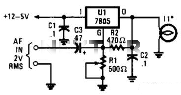
In the visible-light transmitter, a 7805 voltage regulator is configured in a variable-voltage setup, with an audio signal input to modulate the output voltage. The modulated output voltage is utilized to transmit information through an incandescent lamp. The visible-light transmitter...

The circuit utilizes the TCM1506 ring detector/driver integrated circuit, which is a monolithic IC designed to replace mechanical bells in telephones. It is powered and activated by the telephone line's ringing signal, which ranges from 40 to 150 V...