
Mains Operated LED Circuit

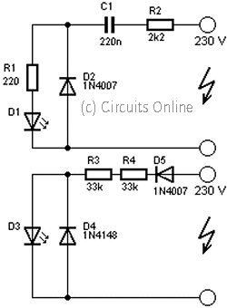
The described LED circuit operates on the principle of using a series combination of resistors and a capacitor to limit the current flowing through the LED. The circuit is connected directly to the AC mains, which allows it to illuminate the LED without the need for a transformer or additional power supply components.
In this configuration, R1 and R2 are chosen based on the desired brightness of the LED and the maximum current rating of the LED. Typically, these resistors are valued to allow a safe current to flow through the LED, which is usually rated for around 20 mA for standard applications. The capacitor C1 serves a dual purpose: it not only helps in current limiting but also provides a phase shift that allows the LED to operate effectively with the alternating current.
The immunity to voltage spikes and surges is achieved through the proper selection of components and their ratings. The resistors must be able to withstand the maximum voltage that may appear across them, while the capacitor should have a voltage rating significantly higher than the maximum expected AC voltage to avoid breakdown.
This LED circuit can be utilized in various applications, including as a power indicator for appliances, a night lamp for low-light environments, or as a simple visual alert for various electronic devices. Its simplicity and effectiveness make it a popular choice for both hobbyists and professionals in the field of electronics.Here is a simple and powerful LED circuit that can be operated directly from the AC 100 volt to AC 230 Volts mains supply. The circuit can be used as mains power locator or night lamp etc.. The resistor R1,R2 and capacitor C1 provides necessary current limiting. The circuit is sufficiently immune against voltage spikes and surges.. 🔗 External reference
Related Circuits

A series of LEDs that turn on and off in a precise sequence, creating a calming and hypnotic effect. Various LED chaser, scanner, and sequencer circuits exist, utilizing discrete transistors, logic integrated circuits (ICs), or microcontrollers. However, a common...

This circuit is based around HT2050 manufactured by HOLTEK semiconductors. It is a low cost, low-power C-MOS LSI designed for lamp and LED flash driver. It requires minimum external components. You can operate it with just two AAA cells...

New design techniques in LED driver circuits promise to deliver significant energy savings that will help TV manufacturers meet stringent power consumption requirements. The advancement of LED driver circuits through innovative design techniques has the potential to yield substantial energy...
This circuit is used to power an LED with a voltage of 230V. The 230V must be reduced to meet the LED's voltage requirements. To achieve this, a circuit is necessary as described below. The circuit designed to power an...

The FM telephone circuit is constructed on a compact PC board that can be easily integrated into the housing of a telephone, functioning as a pseudo-speak earphone. This FM circuit connects in series with the telephone line, drawing power...
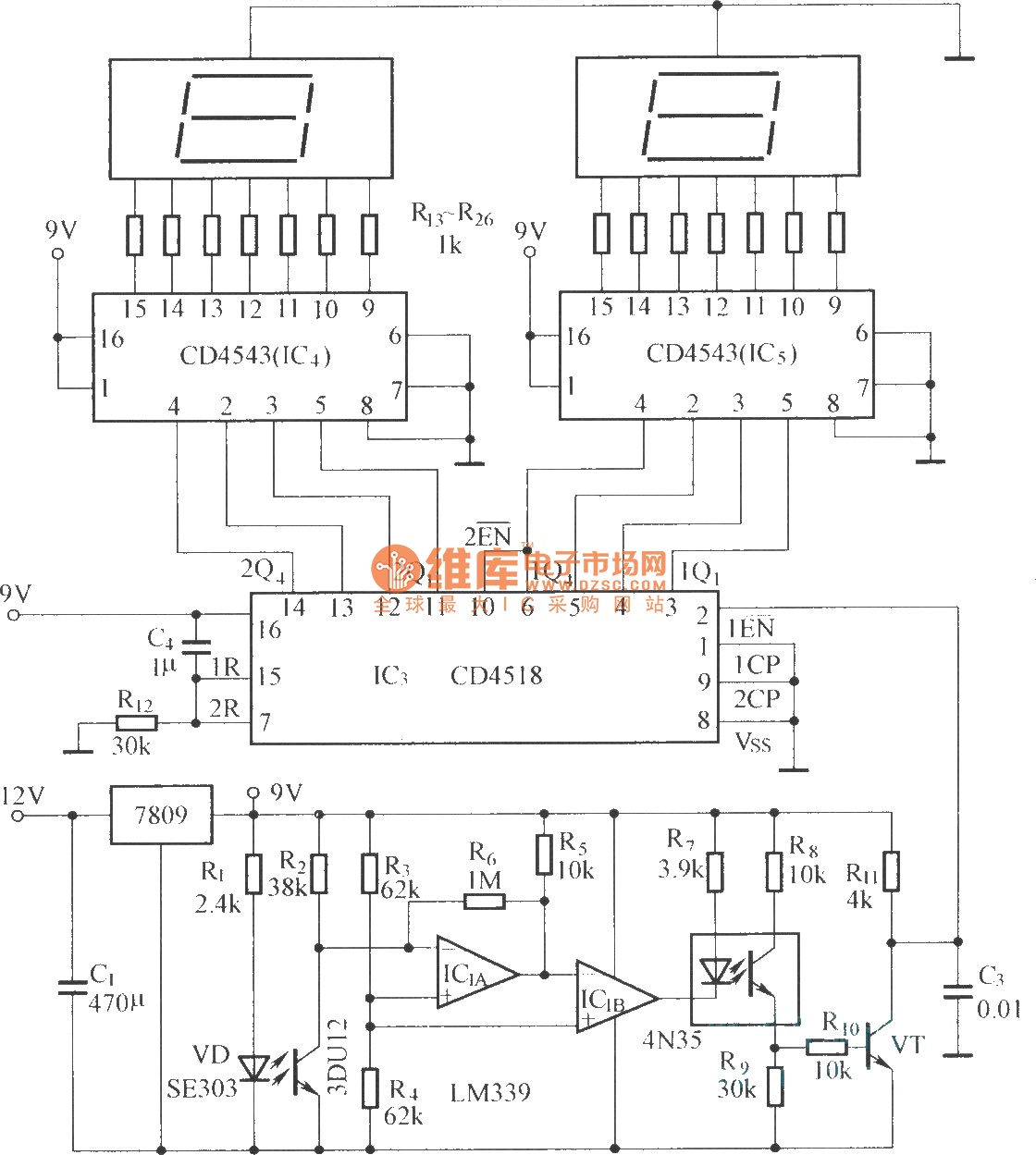
The circuit includes an optical input circuit (VD, 3DU12), a pulse forming circuit (IC1A, IC1B functioning as a voltage comparator; optical coupler; transistor switching circuit), and a counting and display circuit. The circuit architecture consists of several key components that...