
Simple Electromagnetic Field Detector Schematic

This circuit operates as an electromagnetic field detector, leveraging a radial inductor as a sensitive probe to capture low-frequency electromagnetic radiation. The design is straightforward, with a focus on utilizing readily available components. The inductor, with a value of 1mH, serves as the main sensing element, converting changes in magnetic fields into electrical signals. The choice of op-amp, particularly the LF351, enhances the circuit's performance by minimizing noise, which is crucial when detecting low-level signals.
The gain control provided by the 2.2M potentiometer allows for fine-tuning of the output signal, enabling the user to adjust the sensitivity based on the environmental conditions or the specific application. The output is designed to interface with headphones, making the circuit user-friendly for real-time audio feedback. The inclusion of a 3.5mm stereo plug facilitates easy connection and disconnection of the probe, enhancing the circuit's versatility.
The circuit's ability to detect hidden wiring, even when buried under plaster, showcases its practical applications in various fields, including electrical maintenance, safety inspections, and even hobbyist electronics projects. The effective range of detection for transformer hum and the interference from domestic appliances demonstrates its utility in identifying electromagnetic fields in everyday environments.
Future enhancements, such as the implementation of a meter output, would provide a visual representation of the detected fields, further increasing the circuit's functionality and ease of use. Overall, this circuit serves as a valuable tool for those interested in exploring the electromagnetic fields present in their surroundings.This circuit is sensitive to low frequency electromagnetic radiation and will detect for example hidden wiring or the field that encompasses a transformer. Pickup is by a radial type inductor, used as a probe which responds well to low frequency changing magnetic and electric fields.
Ordinary headphones are used to for detection. The field that su rrounds a transformer is heard as a 50 or 60Hz buzz. The circuit is below:- I threaded a length of screened cable through an old pen tube and soldered the ends to a radial type can inductor. I used 1mH. The inductor fitted snugly into the pen tube. The opposite end of the cable connects to the input of the op-amp. Any op-amp should work here, possibly better results may be achieved with a low noise FET type such as the LF351.
The 2M2 potentiometer acts as a gain control and the output is a pair of headphones. Stereo types can be used if they are wired as mono. I used an 8 ohm type, but the circuit should work equally well with higher impedance types. The probe (shown below) may be connected via screened cable and a 3. 5mm stereo plug and socket. The sensitivity of this circuit is good. Mains wiring buried an inch in plaster can be detected with precision. A small load on the electric supply is all that is needed; a 20 watt desk lamp or similar will suffice. The hum field surrounding a transformer can be detected oat over 7 inches. Domestic appliances such as videos and alarm clocks all produce interference which can be heard with the probe.
The electric field surrounding a loudspeaker or earpiece can also be heard. Try lifting a telephone and place the probe near the earpiece. A telephone pickup coil can be used in place of the inductor if desired. I will make an improved version of this circuit with a meter output later. link 🔗 External reference
Related Circuits

This device functions as a convenient tool for testing infrared (IR) remote control transmitters used with televisions, VCRs, and similar devices. The IR signals emitted from a remote control are detected by the IR sensor module within the tester,...
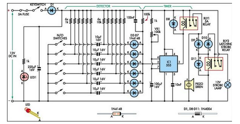
This simple alarm circuit was designed for use in a combined garage and rumpus room. It can be assembled on Veroboard and uses just one IC plus a handful of additional components. The alarm circuit is based on a single...
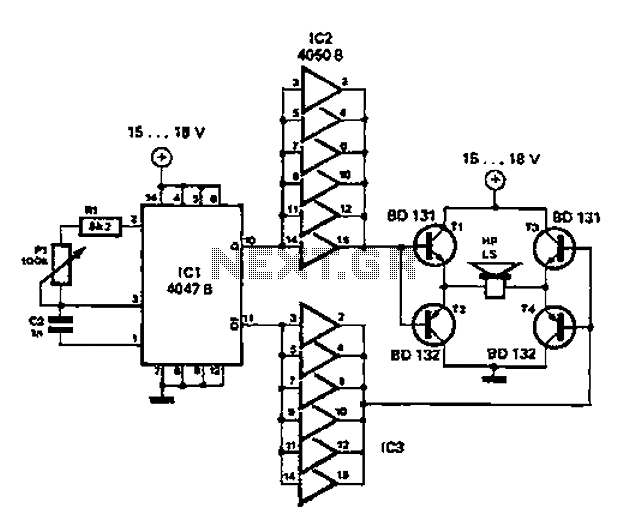
A low-cost and straightforward repellent circuit can be utilized for deterring rats, mice, and other animals, as illustrated in the electronic figure below. The circuit employs a CMOS integrated circuit of type 4047, which functions as a relaxation oscillator....
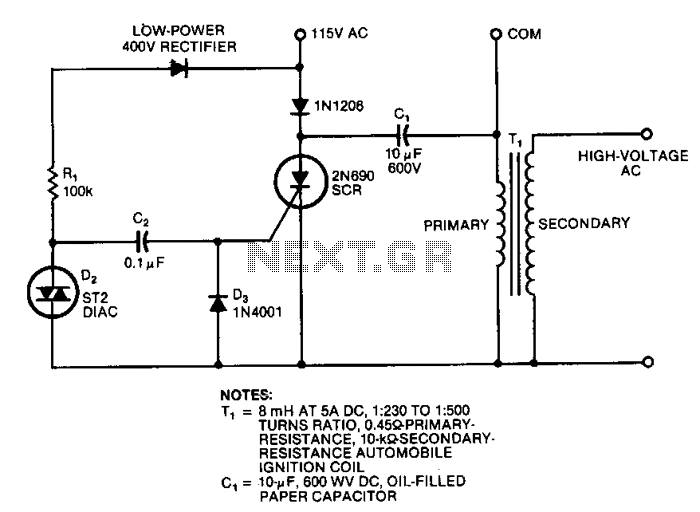
This circuit generates high-voltage pulses using an inexpensive auto ignition coil. By adding a rectifier to the output, the circuit produces high-voltage direct current (DC). The input to the circuit is 115 Vac. During the positive half cycle of...
This figure illustrates the schematic diagram of a simple inductance meter. U1 is a 74LS00 two-input quad NAND gate logic integrated circuit. Two resistors, a capacitor, and a surplus microprocessor crystal create a stable crystal oscillator operating close to...
The circuit illustrates the use of a 555 Timer IC in an infrared (IR) detector configuration. It features a duty cycle of 0.8 milliseconds, a frequency of 120 Hz, and a peak current of 300 mA. The 555 Timer IC...