
Simple Light Sensor Circuit Features High Dynamic Range
The circuit is designed to provide a reliable and accurate measurement of ambient light intensity, making it suitable for various applications in energy harvesting and environmental monitoring. The choice of the BPW21R photocell ensures a high sensitivity and dynamic range, essential for applications that require precise light measurements. The use of the LMC555 timer in the configuration allows for flexible frequency output, which can be easily interfaced with microcontrollers or other digital devices for further processing or data logging. The careful selection of capacitors and resistors is crucial to maintain the integrity of the measurements, particularly in varying environmental conditions. The waterproof enclosure provides additional durability, allowing for outdoor deployment without the risk of damage from moisture or other environmental factors. Overall, this circuit represents a robust solution for ambient light measurement, capable of functioning effectively across a wide range of conditions and applications.Ambient light is increasingly being used as a source of energy. To help designers of such systems, this circuit accurately measures ambient light intensity over four decades of measurement. The design is highly cost effective and, with the sensor mounted in a waterproof glass enclosure, can be deployed in the field for continuous monitoring in all
weather conditions. The sensor in this application, a BPW21R photocell (from Vishay), is used to generate photocurrent proportional to the ambient light intensity ( see the figure ). A photovoltage measurement technique would not offer the high dynamic range desired. The LMC555 CMOS timer converts the photocurrent from the BPW21R into a transistor-transistor-level (TTL) frequency source (10 Hz to 100 kHz).
Any other equivalent timer IC can also be used, but component quality is very important in order to get high dynamic range with accurate measurements. Capacitor C1 should be an NPO/COG or X7R type. NPO/COG capacitors have the lowest temperature coefficient and minimize frequency drift with temperature.
C2 is a filter capacitor for the comparator voltage references. C1 and resistor R1 are timing elements. While charging time depends on the photocurrent from the BPW21R and the value of C1, the discharge time for C1 depends on its capacitance and the resistance of R1. Since both charging time and discharge time contribute to the output`s frequency, it`s important to select R1 to keep the discharge time as low as possible.
In this case, R1 is 1 k © and C1 is 1 nF, making the discharge time 1 µs. The photocell`s dark current is about 2 nA and its maximum output is about 60 µA at saturation level. The cell`s linear sensitivity is 9 nA/lx or 9 µA/klx. This high dynamic range allows the photocell to operate from 10 nA to 50 µA easily. The high-level pulse width (TH) is inversely proportional to the light intensity and can be used for very accurate measurements.
The low-level pulse width (TL) remains constant and isn`t significantly affected by the photocurrent unless R1 is greater than 100 k ©. R1`s value can be selected according to the application and the detection capability of the frequency-measuring device.
As noted earlier, an R1 of 1 k © is ideal for a fast measurement device. For slow measurement devices, like a microcontroller, R1 can be as high as 100 k ©. Increasing the value of R1 reduces the circuit`s linearity at high photocell currents, because TL becomes comparable to TH. However, if the measurement technique uses only TH, R1 can be as high as 100 k © without affecting measurement accuracy.
If R1 is larger than 100 k ©, the voltage drop increases across the resistance and the voltage decreases across the photocell. This causes the photocell to operate in a nonlinear region, which is undesirable. Therefore, the best range for R1 is from 1 k © to 100 k ©. Resistor R2 is 50 ©, which is suitable for driving the output signal over several hundred meters of RG58 coaxial cable to a remote measurement room.
An important advantage to this circuit is that the power source can range from 5 V to 12 V without seriously affecting its operation. That and the circuit`s very low current draw allow the design to operate off a standard 9-V battery. 🔗 External reference
Related Circuits
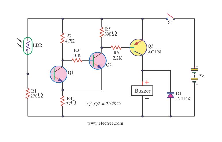
This circuit activates a warning when it becomes dark, functioning as a light-sensitive switch. The essential electronic components include the 2N2926 and AC128 transistors. The described light-sensitive switch circuit is designed to detect ambient light levels and activate an output...
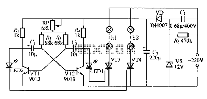
The circuit utilizes a thyristor-controlled unidirectional flashing light string controller. Diodes VT1 and VT2 are connected to a multi-oscillator. Upon powering the circuit, VT1 and VT2 alternately turn on and off. When VT1 is deactivated, VT2 is powered by...
This sound-activated switch allows for control through sound, which can be beneficial not only in robotics but also in home automation applications. The sound-activated switch operates by detecting specific sound frequencies or patterns, typically using a microphone or a sound...

The objective of the circuit is to create an electronic dice using the functionality of a 555 timer integrated circuit operating in astable mode. The electronic dice circuit utilizes a 555 timer configured in astable mode to generate a series...
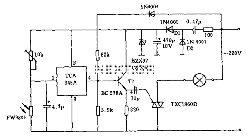
A 200W lamp switch control operates at a power supply voltage of 220V. It automatically turns the light on or off based on ambient illumination levels, specifically activating at approximately 100 lux. In low light conditions, a time-sensitive resistor...
The main ΣΔ loop operates in steady state and is fully controlled by summing comparator Q2. This comparator amplifies the ripples of the sensed inductor current and output voltage with gains KI and KV, respectively, to generate an internal...