
Speed controller circuit change please help

To design a PWM (Pulse Width Modulation) controller using a sawtooth generator, the circuit requires a regulated 7.5V power supply, which ensures that the peak-to-peak voltage (Vpp) of the sawtooth waveform reaches 5V. The sawtooth signal is then fed into one input of a comparator, while the voltage from the manifold absolute pressure (MAP) sensor is connected to the other input. The comparator's output will drive a MOSFET transistor, which acts as a switch to control the power delivered to the load, in this case, an electric motor.
The MAP sensor is crucial in this setup as it provides a voltage output that varies with the air pressure in the manifold. As air pressure increases, the voltage output from the MAP sensor also increases, allowing for dynamic control of the motor's speed. The relationship between the MAP sensor output and the motor speed is essential for achieving the desired performance, particularly in applications such as turbocharged engines where air pressure can significantly affect engine dynamics.
For effective operation, the MAP sensor must be selected based on the pressure range it will experience. Standard MAP sensors may only output voltages up to a certain threshold, meaning that for applications with higher manifold pressures, a sensor capable of handling those conditions must be utilized. Additionally, the output voltage from the MAP sensor has a baseline offset, which must be accounted for in the design.
In more complex implementations, a microprocessor can be integrated into the system to interpret the MAP sensor's output and adjust the PWM signal accordingly. This allows for a more sophisticated control strategy that can account for non-linear relationships between pressure and fuel flow, optimizing the performance of the engine under varying conditions. The microprocessor can also manage additional components such as fuel injectors and a rising rate fuel regulator, which are vital for maintaining the appropriate air-fuel mixture, especially during boost conditions.
Furthermore, considerations regarding the existing engine control unit (ECU) must be addressed. If the engine is equipped with an older ECU or operates mechanically, the integration of additional components may require careful planning to ensure compatibility and compliance with local emissions regulations. Understanding the regulatory environment is critical, as modifications to the engine could have implications for emissions testing and legal compliance.
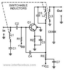
In summary, the successful implementation of a PWM controller in conjunction with a MAP sensor involves careful selection of components, a clear understanding of the system's operational requirements, and consideration of broader regulatory and compatibility issues. This comprehensive approach ensures that the project meets performance goals while remaining within legal boundaries.To make your own PWM controller, start with this sawtooth generator. Run it from a 7. 5V regulated supply to make its Vpp 5V. Feed the sawtooth to one input of a comparator and the MAP voltage to the other input of the same comparator. Let the output drive a MosFet transistor. Hi, thanks for the replie, I`ve found this wiring diagram for the sp eed controler, I`ve drawn on a schematic diagram of the MAP sensor, I`m looking to get the speed controler to increase RPM of a electric motor in step with the air pressure sensed. Having replaced the trimpot with the MAP sensor, the load( in this case a 12v bulb) is shining quite bright with no air pressure applied- when air pressure is applied the bulb shines slightly brighter.
It may be helpful if you explain what exactly you are trying to do. I strongly suspect that there is a flaw or a misunderstanding in your project several steps earlier than the motor controller. All the turbo charged cars I`ve had in the past (ok, only 2) have had a fuel pump that provides a far greater flow than required with the excess being returned to the fuel tank or shunted around the pump via a pressure relief valve of some sort.
Sounds like you trying to turbocharge a NA (normally aspirated) engine. Even though this is not an engine forum, you really need to provide the big picture for people to really help you. Incomplete questions will get incomplete answers that will leave you chasing your tail. As for the MAP sensor, pressure sensors produces a voltage proportional to the pressure plus a constant offset.
So at vacuum, the sensor may produce 0. 5V and at 30" it may produce 4. 5V. If you have a turbocharger that boosts the manifold pressure to 45" your sensor is only going to give you a little over 4. 5V because that is all it is able to put out. I`m adding a turbo to F/I engine( I`ve built several carb` turbo systems ), looking at adding fuel injectors with their own fuel pump & with a rising rate fuel regulator.
Hopefully this will enable me to add the correct fuel ratio when on `boost`. ( modulating the fuel pressure will add/ reduce the fuel flow out of the injectors. Also, this will be used for a water injection system, I know you can buy systems allready however, several friends also will use this system & it will be a great project to get working well! Thanks for the input, the system will be in addition to whats allready running the engine. So the stock ECU will be doing it`s thing & then the added injectors etc, would fatten up the fuel curve when seeing boost It`s job satisfaction !
thats what motivates me. If you add up the man hours I`ve spent on this & other projects it would not be worth it, however self education & helping other people make it worth while. Everything you are trying to do is doable, but not the way you are trying to do it. You will have to change the MAP sensor to one that can work at the higher pressure. The final relationship between the MAP output and the pump voltage is not going to be as simple as you are hoping.
You will likely have to add a microprocessor that will increase the fuel flow based on the pressure via a non-linear relationship. While you do all of this, what is happening with the engine`s native ECU Is it an old enough engine that it does not have an ECU and everything is mechanical What are the regulations for driving this things on public roads Will you still be able to pass emissions if your state has periodic emissions testing If your state does not have annual testing, does it have emissions rules that you are violating anyway You can get away with breaking those rules (if they exist) till you get caught at which time you may be facing some huge fines.
If you are providing this to friends, you may have additional problems. You should look into that angle and understand what risks you are taking. Where are you located Just because there is no annual inspection does not mean there ar 🔗 External reference
Related Circuits
This is a Class D audio amplifier circuit that is used to control PWM motor speed. This circuit has two advantages for battery-powered portable devices. First, The Class D audio amplifier circuit is designed to efficiently manage the speed...
This page presents several transistor circuits that are not commonly found on other pages due to the absence of a specific topic. These circuits, however, illustrate particular points but lack detailed descriptions. An example of an RF amplifier circuit...
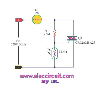
This is an automatic light dimmer circuit. There is no need to manually adjust the brightness of the lights. This circuit is highly convenient, as it utilizes a light-dependent resistor (LDR) to detect external light levels. The automatic light dimmer...
This page is provided to the domain owner free by Sedo's Domain Parking. Disclaimer: The domain owner and Sedo maintain no relationship with third-party advertisers. References to any specific service or trademark are not controlled by Sedo or the...
PWM is a device that can be utilized as an efficient light dimmer or DC motor speed controller. Function: for a general-purpose device that can... PWM (Pulse Width Modulation) is a versatile technique widely employed in various electronic applications, particularly...

This circuit is designed for a UHF TV antenna and provides a 15 dB preamplification. It is constructed using a transistor and minimal components. The schematic features the BF180 UHF transistor. The first stage consists of a band-pass filter...