
Spring Reverb circuit
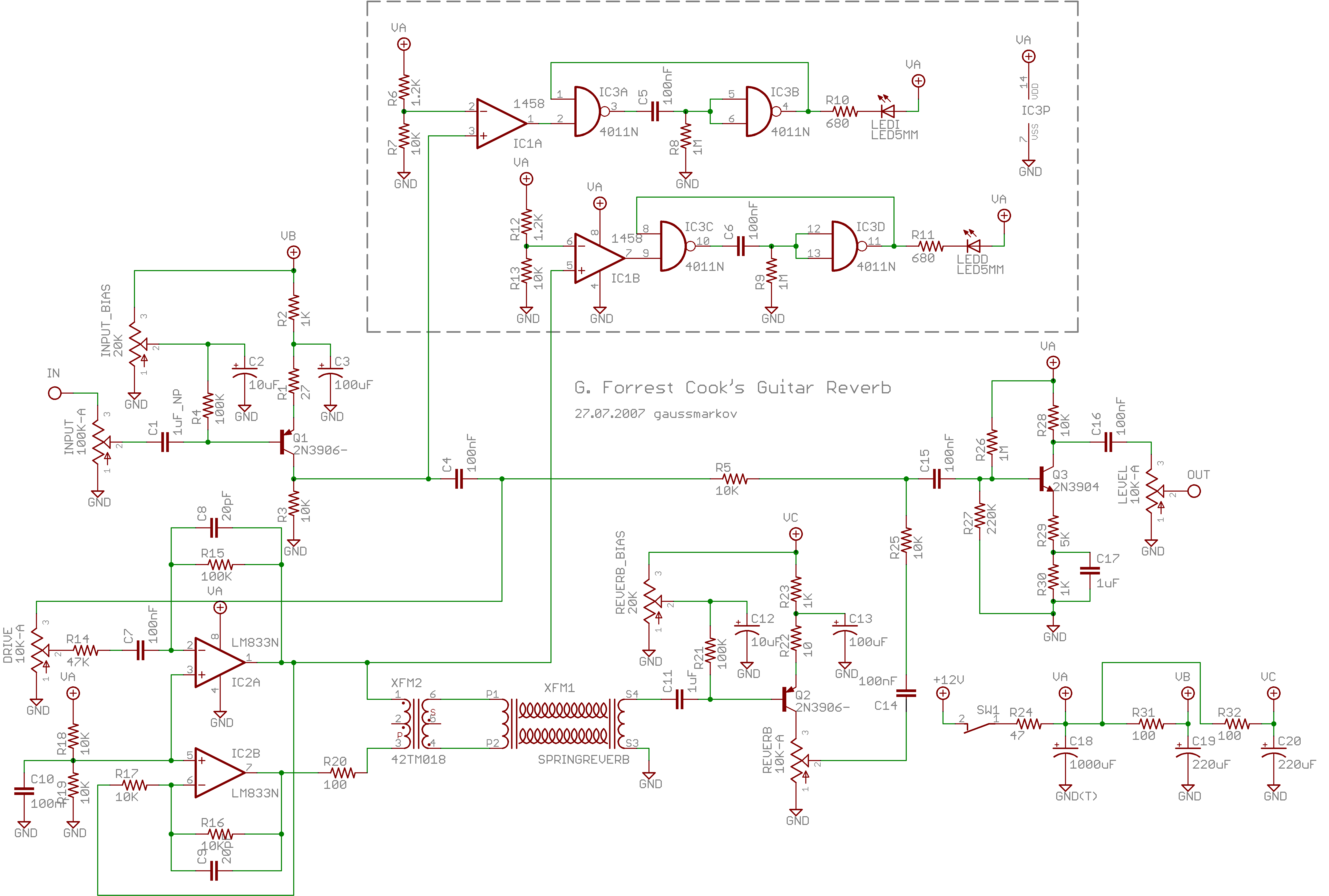
Spring reverb is an analog sound processing technique that utilizes a set of metal springs to generate reverberation effects. The core of the circuit involves a transducer that converts an audio signal into mechanical vibrations, which travel along the springs. At the other end of the springs, another transducer captures the vibrations and converts them back into an audio signal. This process creates a unique, resonant sound that can enhance musical performances or recordings.
In a typical spring reverb circuit, the audio input is fed into a driver circuit that excites the springs. The driver often includes an operational amplifier configured to provide sufficient gain and control over the signal. The springs themselves are usually housed in a metal chassis to prevent external noise interference.
The output from the receiving transducer is then processed through an equalization stage to tailor the frequency response of the reverb effect. This stage can include passive or active components, allowing for adjustments to enhance the tonal quality of the reverberated sound.
Additional features may include control knobs for adjusting the reverb depth, decay time, and mix level, enabling users to fine-tune the effect to their liking. Spring reverb circuits are often integrated into guitar amplifiers, synthesizers, and standalone effects units, making them versatile tools for sound design. The ability to create both subtle ambiance and dramatic explosive effects makes spring reverb a popular choice among musicians and audio engineers.spring reverb It sounds really clean and natural almost too good to be a spring reverb. But when you whack the reverb springs - *POW* - you get dub explosions.. 🔗 External reference
Related Circuits
A buzzer circuit utilizes a PIC microcontroller to drive a piezo buzzer. The microcontroller is a low-power processor that is ideal for portable and compact devices where battery conservation is essential. The buzzer circuit employs a PIC microcontroller, which serves...
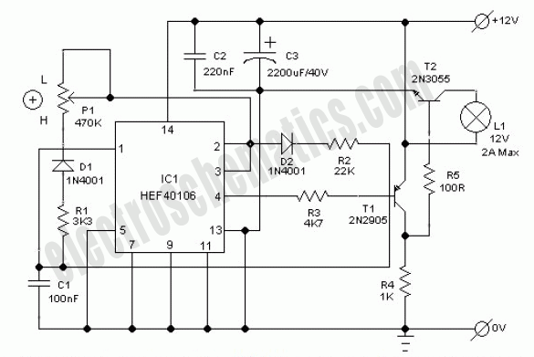
This electronic lighting dimmer circuit is designed to control the brightness of incandescent lamps, but it is not suitable for fluorescent lamps. It operates with both 110V and 220V AC power sources. The circuit is connected in series with...
If the transmitter stick-potentiometer delivers a voltage about 2 - 3 V, this circuit will be suitable. If you want to avoid using the battery cable (supplying Vcc for IC1 and -2), you can use a separate 5V supply...
Ensure that connections are verified against the circuit diagram and schematic provided below. This can be utilized while following the tutorial video. The circuit diagram serves as a crucial reference for accurately assembling electronic components in a project. It illustrates...
This LED table or reading lamp circuit can be utilized for various applications, such as a reading lamp for a bed, a desktop or table lamp, a keyboard lamp (to illuminate the keys of a computer keyboard in low...
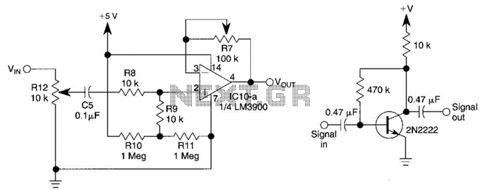
This circuit utilizes one-quarter of an LM3900 to create a simple variable-gain front end for an oscilloscope. R7 serves as the gain control. Additionally, a basic preamplifier is included for applications requiring more than 10X gain. The circuit employs the...